 jlbrian7
x10 library from here:
https://github.com/pyrou/X10RF-Arduino
there were a couple of bugs, but the biggest problem is that I don't have the radio communicating yet.
#include <SPI.h>
#include <RH_RF95.h>
#include <x10rf.h>

/* for feather32u4 */
#define RFM95_CS 8
#define RFM95_RST 4
#define RFM95_INT 7

#define tx 2 				// Pin number for the 433mhz OOK transmitter
#define reps 5 				// Number of times that a RF command must be repeated.
#define clkpin 3
#define ledpin 13 //BLUE_LED 	// Pin for the led that blinks when a command is send. (0 = no blink)

// Change to 434.0 or other frequency, must match RX's freq!
#define RF95_FREQ 433.96

#define ON     0x00
#define OFF    0x20
#define BRIGHT 0x88
#define DIM    0x98

// Singleton instance of the radio driver
RH_RF95 rf95(RFM95_CS, RFM95_INT);

x10rf myx10 = x10rf(tx,clkpin,ledpin,reps);

void setup()
{
  myx10.begin();

  pinMode(RFM95_RST, OUTPUT);
  digitalWrite(RFM95_RST, HIGH);

  while (!Serial);
  Serial.begin(9600);
  delay(100);

  Serial.println("Feather LoRa Radio Test FSK/OOK Mode!");

  // manual reset
  digitalWrite(RFM95_RST, LOW);
  delay(10);
  digitalWrite(RFM95_RST, HIGH);
  delay(10);

  while (!rf95.init()) {
    Serial.println("LoRa radio init failed");
    while (1);
  }
  Serial.println("LoRa radio init OK!");

  if (!rf95.setFrequency(RF95_FREQ)) {
    Serial.println("setFrequency failed");
    while (1);
  }
  Serial.print("Set Freq to: "); Serial.println(RF95_FREQ);
  rf95.setTxPower(23, false);

  rf95.spiWriteRegister(RH_RF95_REG_01_OP_MODE, 0x00);
  rf95.spiWriteRegister(RH_RF95_REG_01_OP_MODE, 0x0B);
  //rf95.spiWriteRegister(RH_RF95_REG_40_DIO_MAPPING1, RH_RF95_DIO_0_2);
  rf95.spiWriteRegister(RH_RF95_REG_30_PACKET_CONFIG_1, 0x80);
  rf95.spiWriteRegister(RH_RF95_REG_31_PACKET_CONFIG_2, RH_RF95_DATA_MODE_CONT);
  Serial.println(rf95.spiReadRegister(RH_RF95_REG_01_OP_MODE), HEX);
  Serial.println(rf95.spiReadRegister(RH_RF95_REG_30_PACKET_CONFIG_1), HEX);
  Serial.println(rf95.spiReadRegister(RH_RF95_REG_31_PACKET_CONFIG_2), HEX);
  Serial.println(rf95.spiReadRegister(RH_RF95_REG_40_DIO_MAPPING1), HEX);

}

void loop()
{
	myx10.x10Switch('A', 1, ON); // Switch D15 off
  Serial.println("A1: On");
  //Serial.println(rf95.spiReadRegister(RH_RF95_REG_3E_IRQ_FLAGS_1), BIN);
  /*uint8_t tempVal = rf95.spiReadRegister(RH_RF95_REG_3C_TEMP);
  int temp = tempVal & 0x7F;
  if ((tempVal & 0x80) == 0x80){
    temp *= -1;
  }
  Serial.println(temp);*/
	delay(3000);

  myx10.x10Switch('A', 1, OFF); // Switch D15 off
  Serial.println("A1: Off");
  delay(3000);
}
Data out to radio, and clock signal from radio being in continuous mode:
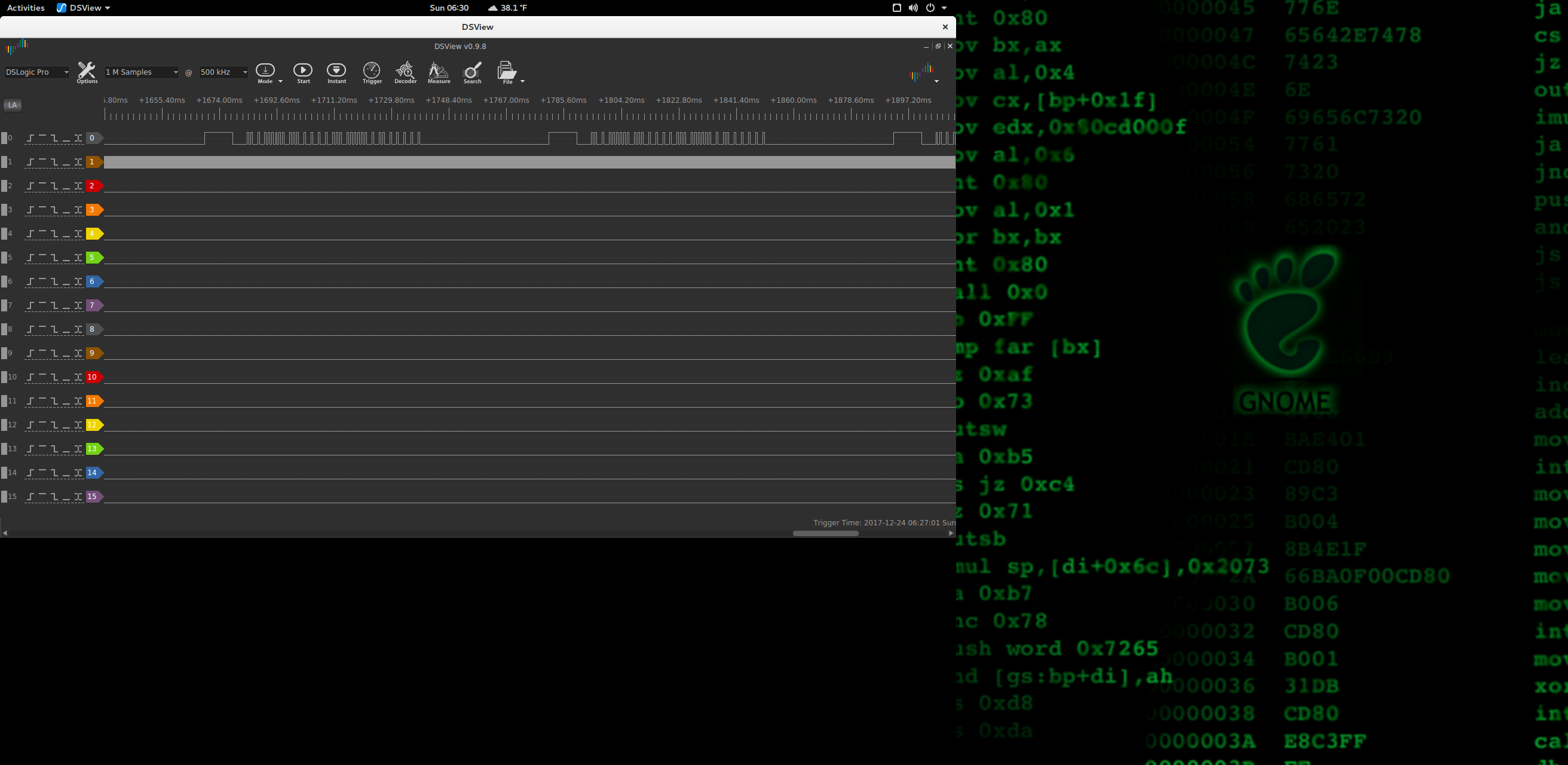
The signal out looks correct, compared to this, which is taken directly from an x10 remote:
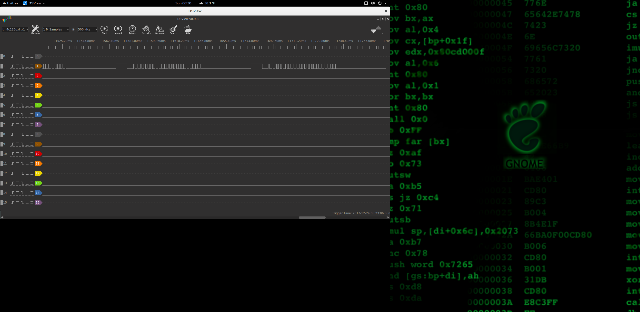
I removed the RF transmitter from the remote, and hooked up the logic analyzer to the pins where the transmitter was in order to check what I was doing against something known and good.
Discussions
Become a Hackaday.io Member
Create an account to leave a comment. Already have an account? Log In.