jlbrian7
-
x10 tm4c123gxl
12/24/2017 at 11:44 • 0 commentsSince I now have a cheap 433MHz transmitter, which I took out of the remote, I hooked it up to my tm4c123gxl in order to test my code.
//*****************************************************************************
//
// blinky.c - Simple example to blink the on-board LED.
//
// Copyright (c) 2012-2016 Texas Instruments Incorporated.  All rights reserved.
// Software License Agreement
//
// Texas Instruments (TI) is supplying this software for use solely and
// exclusively on TI's microcontroller products. The software is owned by
// TI and/or its suppliers, and is protected under applicable copyright
// laws. You may not combine this software with "viral" open-source
// software in order to form a larger program.
//
// THIS SOFTWARE IS PROVIDED "AS IS" AND WITH ALL FAULTS.
// NO WARRANTIES, WHETHER EXPRESS, IMPLIED OR STATUTORY, INCLUDING, BUT
// NOT LIMITED TO, IMPLIED WARRANTIES OF MERCHANTABILITY AND FITNESS FOR
// A PARTICULAR PURPOSE APPLY TO THIS SOFTWARE. TI SHALL NOT, UNDER ANY
// CIRCUMSTANCES, BE LIABLE FOR SPECIAL, INCIDENTAL, OR CONSEQUENTIAL
// DAMAGES, FOR ANY REASON WHATSOEVER.
//
// This is part of revision 2.1.3.156 of the EK-TM4C123GXL Firmware Package.
//
//*****************************************************************************

#include <stdint.h>
#include <stdbool.h>
#include <stdlib.h>
#include "inc/hw_memmap.h"
#include "driverlib/gpio.h"
#include "driverlib/sysctl.h"
#include "driverlib/rom.h"

#define ON     0x00
#define OFF    0x20
#define BRIGHT 0x88
#define DIM    0x98

#define X10_RF_SB_LONG          8960     // Start burts (leader) = 9ms
#define X10_RF_SB_SHORT         4500     // Start silecence (leader) = 4,5 ms
#define X10_RF_BIT_LONG         1120     // Bit 1 pulse length
#define X10_RF_BIT_SHORT        560      // Bit 1 pulse length
#define X10_RF_GAP              40000    // Length between commands

#define bitRead(value, bit) (((value) >> (bit)) & 0x01)
#define bitSet(value, bit) ((value) |= (1UL << (bit)))
#define bitClear(value, bit) ((value) &= ~(1UL << (bit)))
#define bitWrite(value, bit, bitvalue) (bitvalue ? bitSet(value, bit) : bitClear(value, bit))

void x10Switch(char house_code, uint8_t unit_code, uint8_t command);
void SendCommand(uint8_t *data, uint8_t size);
void SendX10RfByte(uint8_t data);
void SendX10RfBit(unsigned int databit);
void SEND_HIGH();
void SEND_LOW();

uint8_t _rf_repeats = 5;

void delayUS(uint32_t us) {
    ROM_SysCtlDelay( (ROM_SysCtlClockGet()/(3*1000*1000))*us ) ;  // more accurate
}

int
main(void)
{
    volatile uint32_t ui32Loop;

    //80Mhz
    //ROM_SysCtlClockSet(SYSCTL_SYSDIV_2_5 | SYSCTL_USE_PLL | SYSCTL_OSC_MAIN | SYSCTL_XTAL_16MHZ);

    //
    // Enable the GPIO port that is used for the on-board LED.
    //
    SysCtlPeripheralEnable(SYSCTL_PERIPH_GPIOF);

    // port used for the transmitter
    SysCtlPeripheralEnable(SYSCTL_PERIPH_GPIOB);

    //
    // Check if the peripheral access is enabled.
    //
    while(!SysCtlPeripheralReady(SYSCTL_PERIPH_GPIOF))
    {
    }

    //
    // Enable the GPIO pin for the LED (PF3).  Set the direction as output, and
    // enable the GPIO pin for digital function.
    //
    GPIOPinTypeGPIOOutput(GPIO_PORTF_BASE, GPIO_PIN_3);

    //enable
    GPIOPinTypeGPIOOutput(GPIO_PORTB_BASE, GPIO_PIN_0);
    GPIOPinWrite(GPIO_PORTB_BASE, GPIO_PIN_0, GPIO_PIN_0);

    //signal
    GPIOPinTypeGPIOOutput(GPIO_PORTB_BASE, GPIO_PIN_5);

    //
    // Loop forever.
    //
    while(1)
    {
        /*//
        // Turn on the LED.
        //
        GPIOPinWrite(GPIO_PORTF_BASE, GPIO_PIN_3, GPIO_PIN_3);

        //
        // Delay for a bit.
        //
        for(ui32Loop = 0; ui32Loop < 200000; ui32Loop++)
        {
        }

        //
        // Turn off the LED.
        //
        GPIOPinWrite(GPIO_PORTF_BASE, GPIO_PIN_3, 0x0);

        //
        // Delay for a bit.
        //
        for(ui32Loop = 0; ui32Loop < 200000; ui32Loop++)
        {
        }*/

        x10Switch('A', 2, ON); // Switch A1 On
        delayUS(3000000);
        x10Switch('A', 2, ON); // Switch A1 On
        delayUS(3000000);


    }
}

void x10Switch(char house_code, uint8_t unit_code, uint8_t command){
    uint8_t x10buff[4]; // Set message buffer 4 bytes
    switch(house_code) {
        case 'A': x10buff[0] = 0b0110; break;
        case 'B': x10buff[0] = 0b0111; break;
        case 'C': x10buff[0] = 0b0100; break;
        case 'D': x10buff[0] = 0b0101; break;
        case 'E': x10buff[0] = 0b1000; break;
        case 'F': x10buff[0] = 0b1001; break;
        case 'G': x10buff[0] = 0b1010; break;
        case 'H': x10buff[0] = 0b1011; break;
        case 'I': x10buff[0] = 0b1110; break;
        case 'J': x10buff[0] = 0b1111; break;
        case 'K': x10buff[0] = 0b1100; break;
        case 'L': x10buff[0] = 0b1101; break;
        case 'M': x10buff[0] = 0b0000; break;
        case 'N': x10buff[0] = 0b0001; break;
        case 'O': x10buff[0] = 0b0010; break;
        case 'P': x10buff[0] = 0b0011; break;
        default:  x10buff[0] = 0;     break;
    }
    x10buff[0] = x10buff[0] << 4; // House code goes into the upper nibble

    x10buff[2] = command;

    /*switch(command) {
      case ON:
      case OFF:
      case BRIGHT:
      case DIM:

    }*/
    // Set unit number
    unit_code = unit_code - 1;
    bitWrite(x10buff[2],6,bitRead(unit_code,2));
    bitWrite(x10buff[2],3,bitRead(unit_code,1));
    bitWrite(x10buff[2],4,bitRead(unit_code,0));
    bitWrite(x10buff[0],2,bitRead(unit_code,3));
    // Set parity
    x10buff[1] = ~x10buff[0];
    x10buff[3] = ~x10buff[2];
    SendCommand(x10buff, sizeof(x10buff));
}

void SendCommand(uint8_t *data, uint8_t size){
    uint8_t i = 0;
    int j = 0;
    GPIOPinWrite(GPIO_PORTF_BASE, GPIO_PIN_3, GPIO_PIN_3);
    for(i = 0; i < _rf_repeats; i++){
        SEND_HIGH();
        delayUS(X10_RF_SB_LONG);

        SEND_LOW();
        delayUS(X10_RF_SB_SHORT);

        for(j=0; j <= size; j++) {
            SendX10RfByte(data[j]);
        }
    SendX10RfBit(1);
    delayUS(X10_RF_GAP);
    }
    GPIOPinWrite(GPIO_PORTF_BASE, GPIO_PIN_3, 0x0);
}

void SendX10RfByte(uint8_t data){
    int i = 0;
    //Serial.println("\n");
    for(i=7; i >= 0; i--){ // send bits from byte
        SendX10RfBit((bitRead(data,i)==1));
        //Serial.print(bitRead(data,i));
    }
}

void SendX10RfBit(unsigned int databit){
    SEND_HIGH();
    delayUS(X10_RF_BIT_SHORT);

    SEND_LOW();
    delayUS(X10_RF_BIT_SHORT);

    if (databit){
        delayUS(X10_RF_BIT_LONG);
    }
}

void SEND_HIGH() {

    GPIOPinWrite(GPIO_PORTB_BASE, GPIO_PIN_5, GPIO_PIN_5);
}

void SEND_LOW(){

    GPIOPinWrite(GPIO_PORTB_BASE, GPIO_PIN_5, 0x0);
}
This code, and the transmitter from the remote had the light flashing on and off just as expected.
So, back to figuring out what I am doing wrong with the radio.
-
x10 Arduino Code
12/24/2017 at 11:39 • 0 commentsx10 library from here:
https://github.com/pyrou/X10RF-Arduino
there were a couple of bugs, but the biggest problem is that I don't have the radio communicating yet.
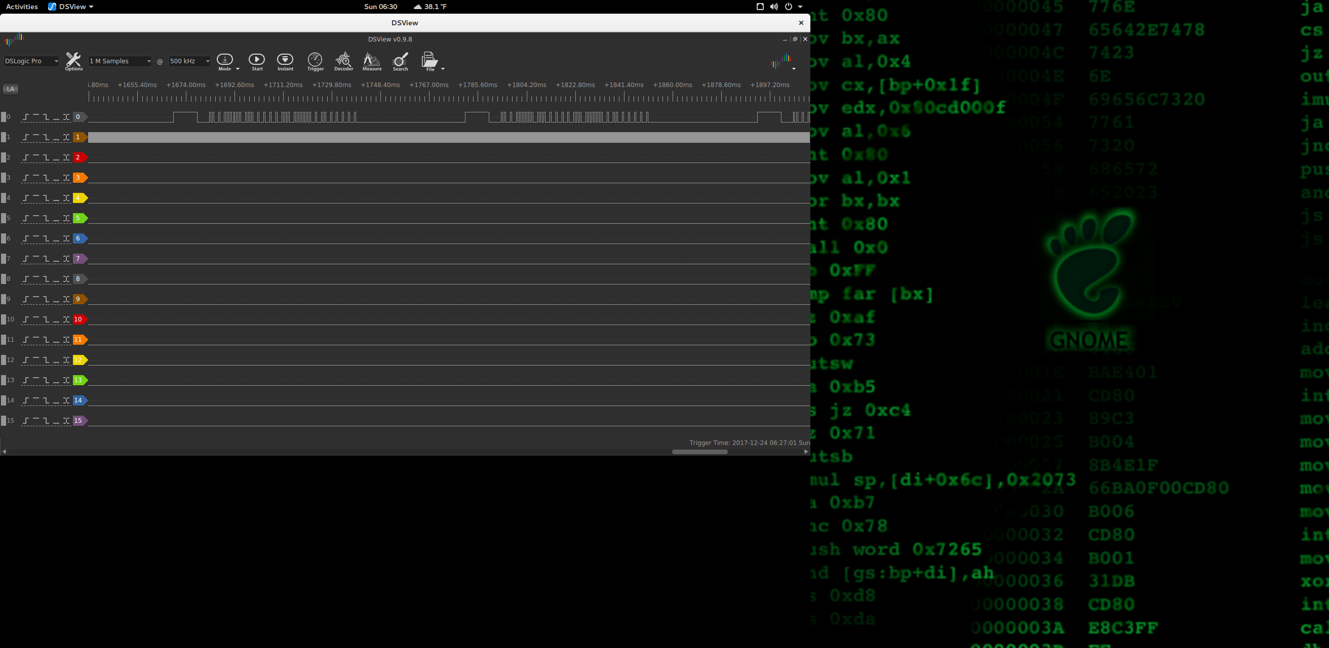
#include <SPI.h>
#include <RH_RF95.h>
#include <x10rf.h>

/* for feather32u4 */
#define RFM95_CS 8
#define RFM95_RST 4
#define RFM95_INT 7

#define tx 2 				// Pin number for the 433mhz OOK transmitter
#define reps 5 				// Number of times that a RF command must be repeated.
#define clkpin 3
#define ledpin 13 //BLUE_LED 	// Pin for the led that blinks when a command is send. (0 = no blink)

// Change to 434.0 or other frequency, must match RX's freq!
#define RF95_FREQ 433.96

#define ON     0x00
#define OFF    0x20
#define BRIGHT 0x88
#define DIM    0x98

// Singleton instance of the radio driver
RH_RF95 rf95(RFM95_CS, RFM95_INT);

x10rf myx10 = x10rf(tx,clkpin,ledpin,reps);

void setup()
{
  myx10.begin();

  pinMode(RFM95_RST, OUTPUT);
  digitalWrite(RFM95_RST, HIGH);

  while (!Serial);
  Serial.begin(9600);
  delay(100);

  Serial.println("Feather LoRa Radio Test FSK/OOK Mode!");

  // manual reset
  digitalWrite(RFM95_RST, LOW);
  delay(10);
  digitalWrite(RFM95_RST, HIGH);
  delay(10);

  while (!rf95.init()) {
    Serial.println("LoRa radio init failed");
    while (1);
  }
  Serial.println("LoRa radio init OK!");

  if (!rf95.setFrequency(RF95_FREQ)) {
    Serial.println("setFrequency failed");
    while (1);
  }
  Serial.print("Set Freq to: "); Serial.println(RF95_FREQ);
  rf95.setTxPower(23, false);

  rf95.spiWriteRegister(RH_RF95_REG_01_OP_MODE, 0x00);
  rf95.spiWriteRegister(RH_RF95_REG_01_OP_MODE, 0x0B);
  //rf95.spiWriteRegister(RH_RF95_REG_40_DIO_MAPPING1, RH_RF95_DIO_0_2);
  rf95.spiWriteRegister(RH_RF95_REG_30_PACKET_CONFIG_1, 0x80);
  rf95.spiWriteRegister(RH_RF95_REG_31_PACKET_CONFIG_2, RH_RF95_DATA_MODE_CONT);
  Serial.println(rf95.spiReadRegister(RH_RF95_REG_01_OP_MODE), HEX);
  Serial.println(rf95.spiReadRegister(RH_RF95_REG_30_PACKET_CONFIG_1), HEX);
  Serial.println(rf95.spiReadRegister(RH_RF95_REG_31_PACKET_CONFIG_2), HEX);
  Serial.println(rf95.spiReadRegister(RH_RF95_REG_40_DIO_MAPPING1), HEX);

}

void loop()
{
	myx10.x10Switch('A', 1, ON); // Switch D15 off
  Serial.println("A1: On");
  //Serial.println(rf95.spiReadRegister(RH_RF95_REG_3E_IRQ_FLAGS_1), BIN);
  /*uint8_t tempVal = rf95.spiReadRegister(RH_RF95_REG_3C_TEMP);
  int temp = tempVal & 0x7F;
  if ((tempVal & 0x80) == 0x80){
    temp *= -1;
  }
  Serial.println(temp);*/
	delay(3000);

  myx10.x10Switch('A', 1, OFF); // Switch D15 off
  Serial.println("A1: Off");
  delay(3000);
}
Data out to radio, and clock signal from radio being in continuous mode:
![]()
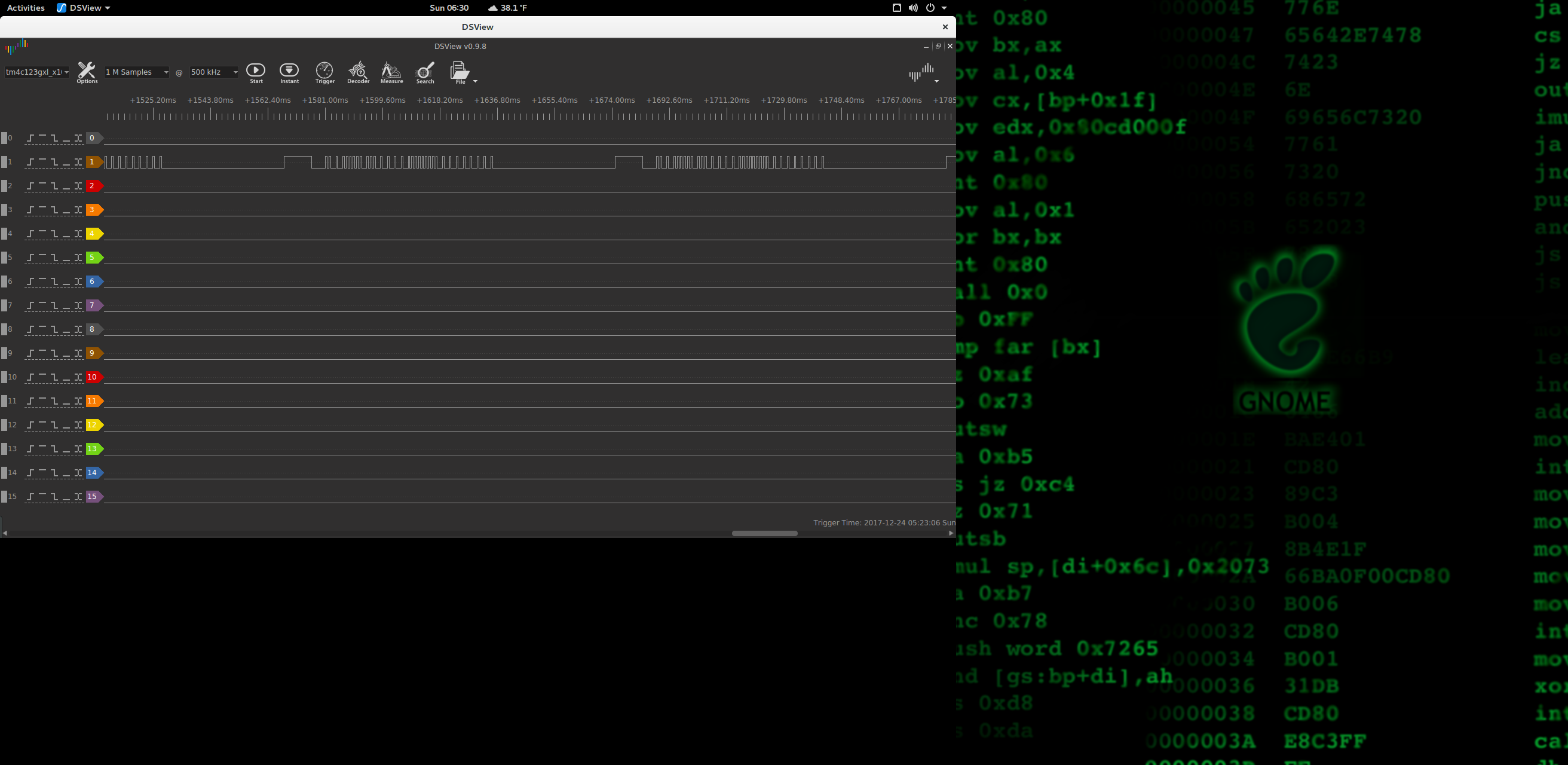
The signal out looks correct, compared to this, which is taken directly from an x10 remote:
![]()
I removed the RF transmitter from the remote, and hooked up the logic analyzer to the pins where the transmitter was in order to check what I was doing against something known and good.
RH_RF95
added the registers and a couple of functions so that FSK/OOK can be used on the Feather 32u4 w/ 433MHz LoRa radio