 Michael Furtak
In my final NeoPixel clock build, I'm planning to have a knob for easy adjustment of the time, and possibly other settings. A rotary encoder works great for this, and this one also has a push button switch, giving us a few inputs in one package.
While the rotary encoder has breadboard-friendly pin spacing, I found that it didn't reliably stay seated in my breadboard. I think the wide, flat pin shape is to blame for that. So, to make it a bit easier to work with, I snapped off a bit of proto board (the kind with breadboard-like connected rows) and broke out the pins.
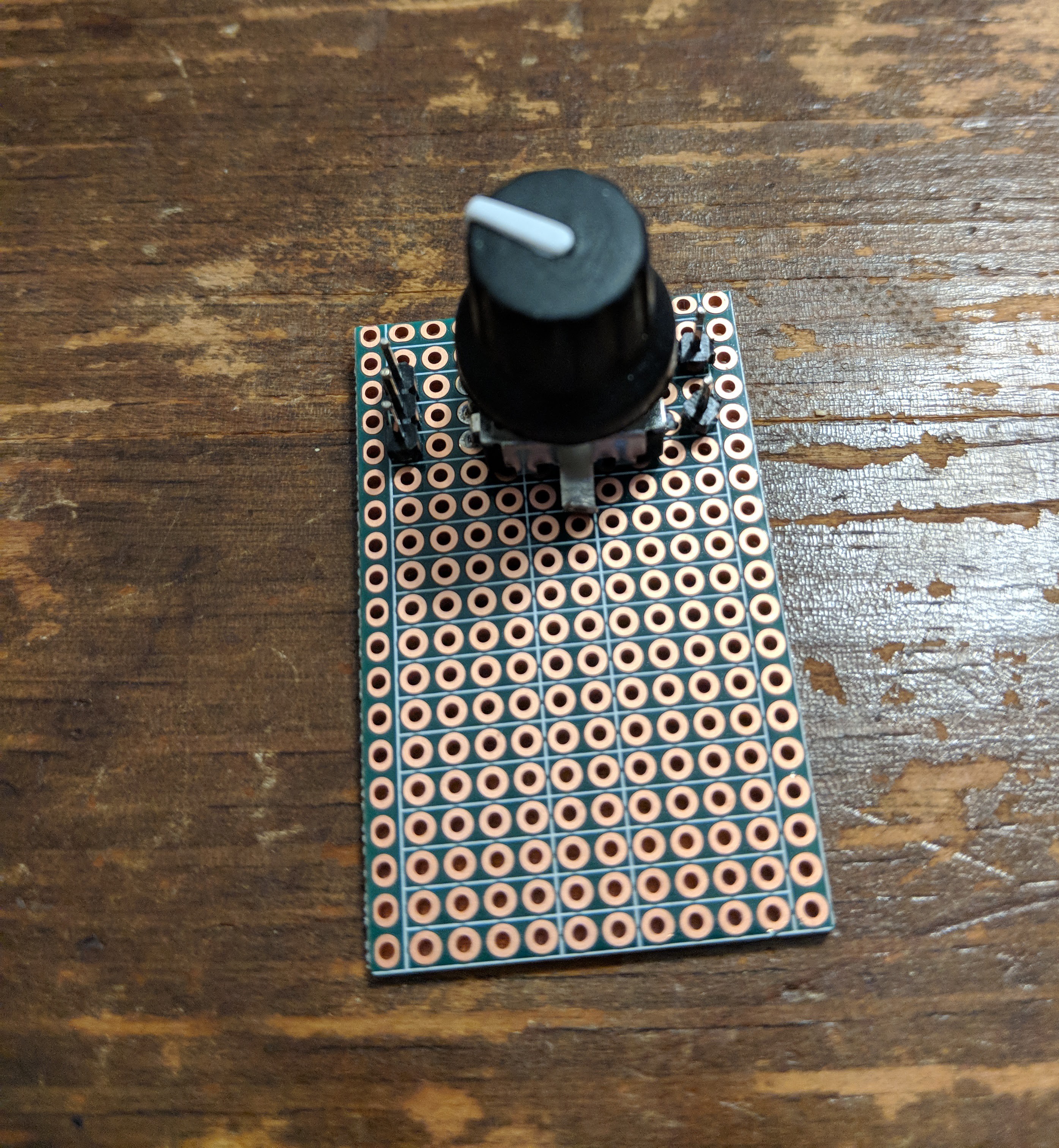
I suppose I could have attached the pins the other way around to then make it easier to reinsert into a breadboard, but with the pins up, I can just connect right back to my Arduino instead.
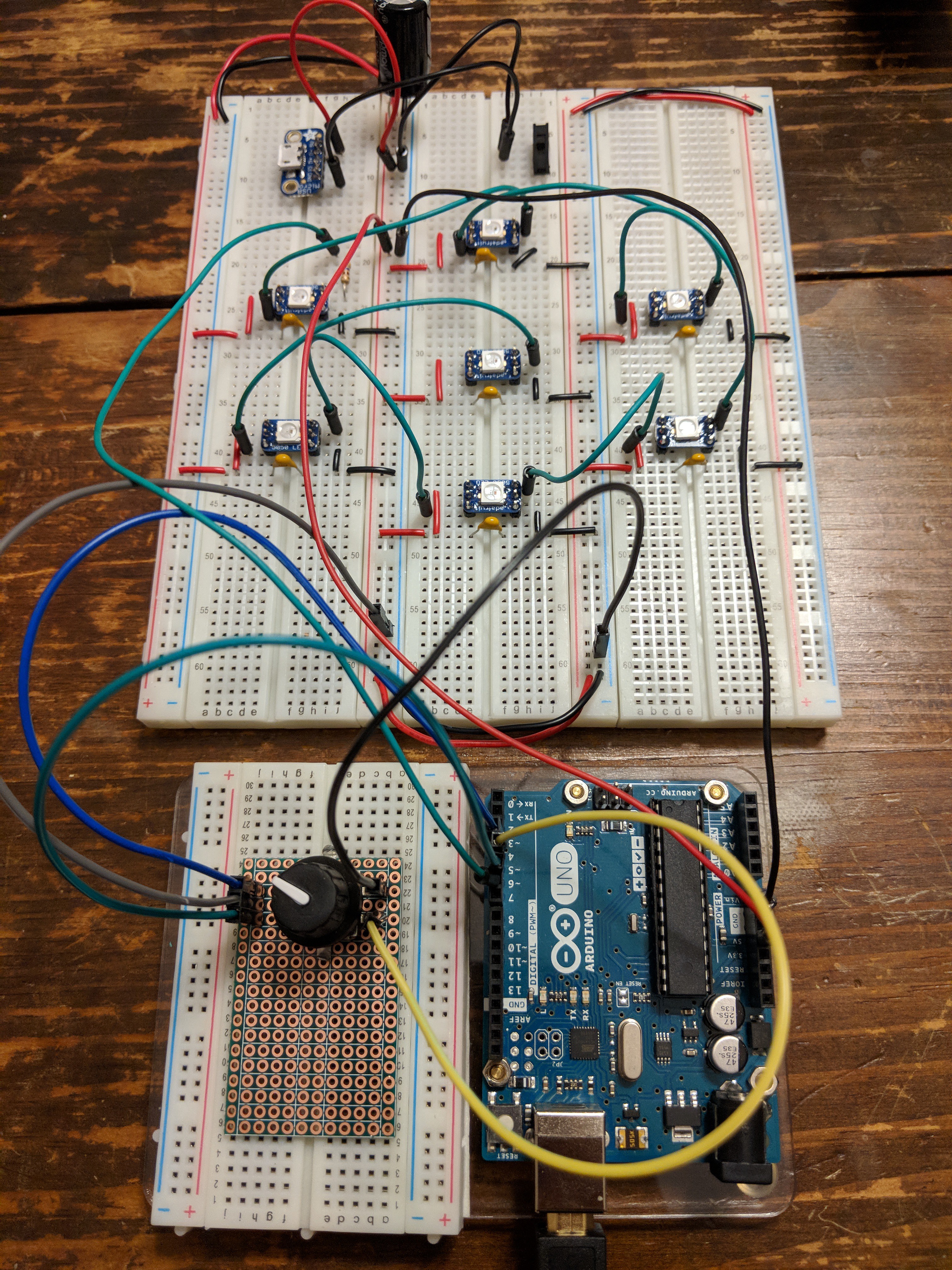
The code for interpreting the rotary encoder signals was modified from the example code here, and it allows me to detect turns left and right on the knob, as well as handling the push button when you press the knob in.
All of that gets me to a demo where I can use knob button presses to switch between 3 modes:
- digit mode
- color mode
- brightness mode
As you would expect, turning the knob in each of those modes adjusts what digit is displayed, in what color, and how brightly!
Discussions
Become a Hackaday.io Member
Create an account to leave a comment. Already have an account? Log In.