 Michael Furtak
It's been about a month since I started working on this project, and the time has come to put it together!
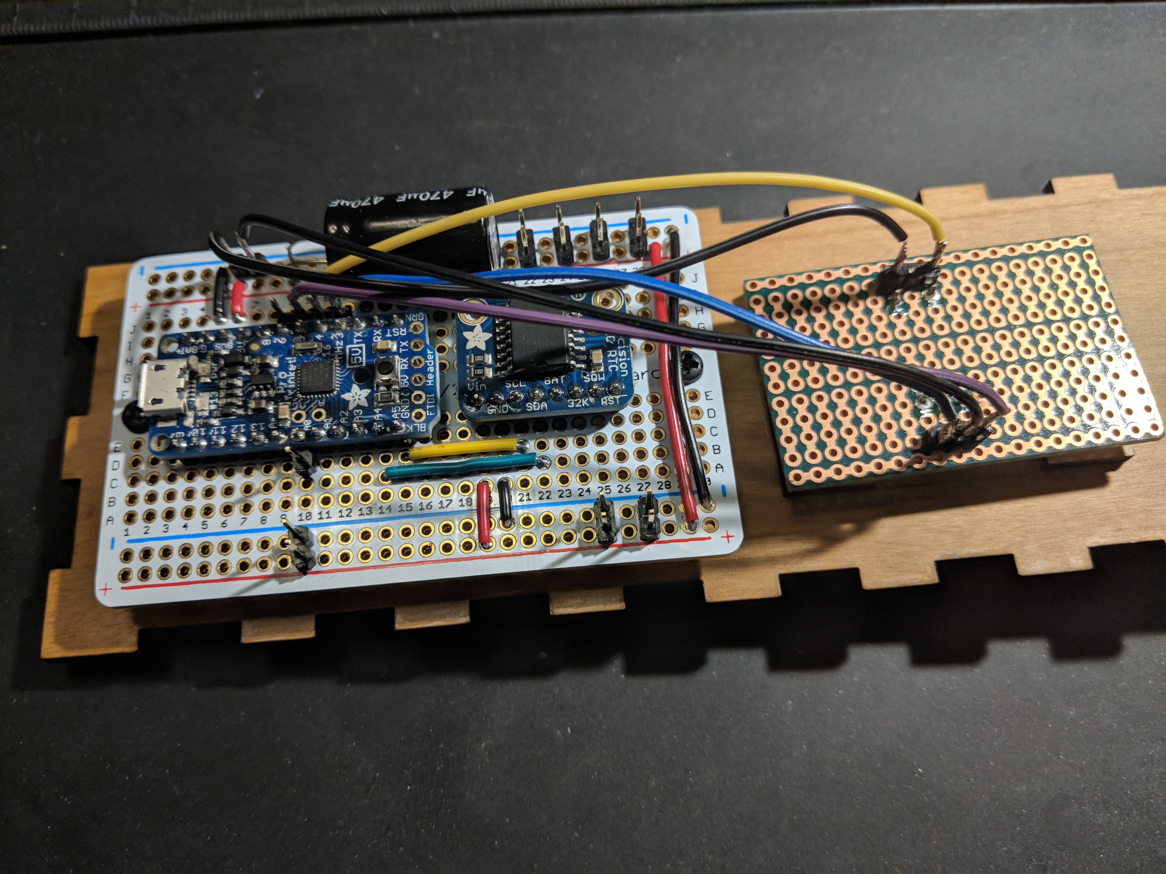
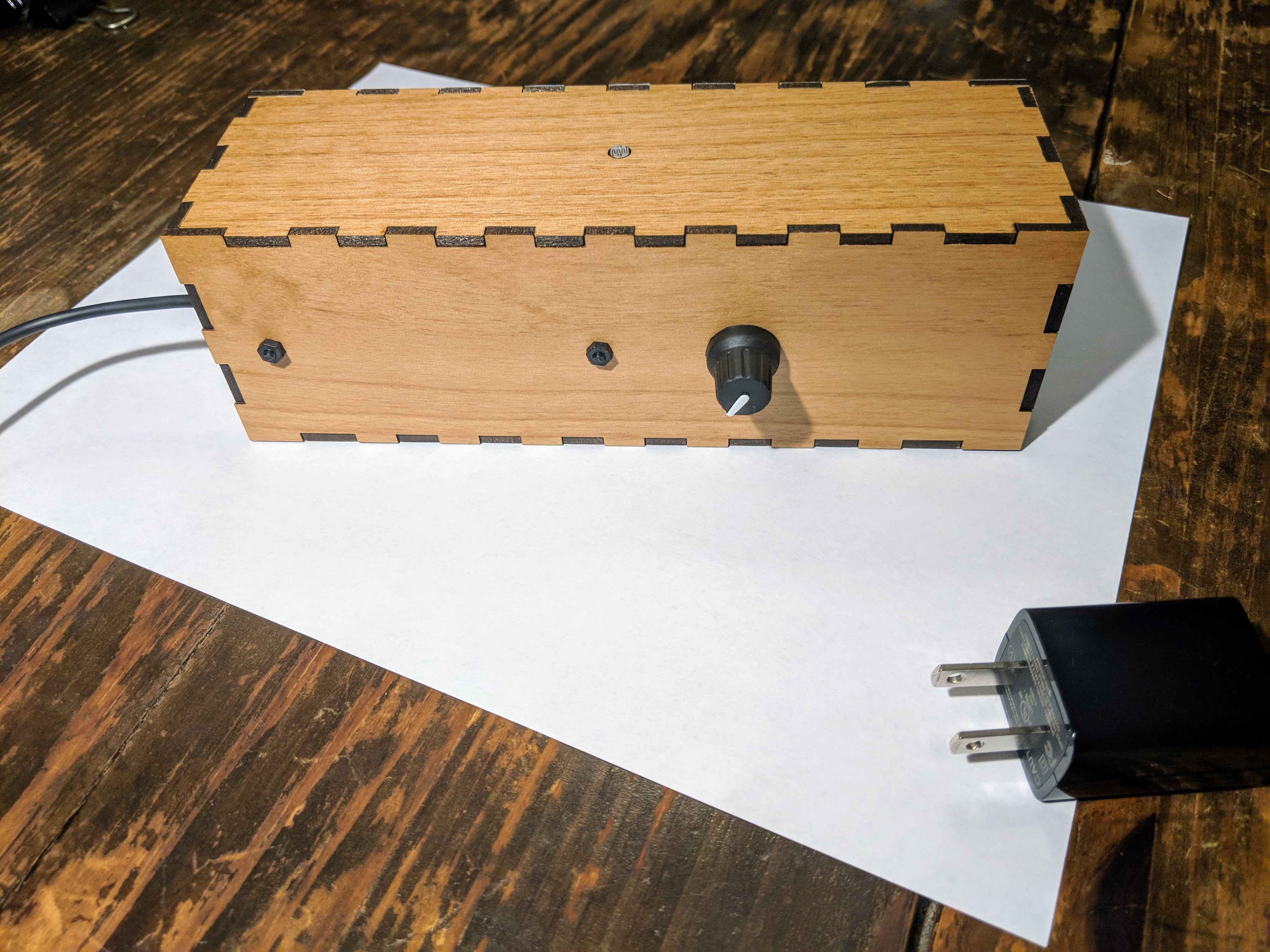
Aside from the main protoboard containing the Adafruit Pro Trinket (5v) and the Real-Time Clock (RTC) module, there are a couple other small boards that support the other functions. One has the rotary encoder which is mounted on the back of the box, next to the main board. The other holds the CdS photoresistor, and is mounted on the inside of the top of the box, with the photocell exposed through a hole. A bit of hot glue keeps that attached, since I didn't plan for a better method.
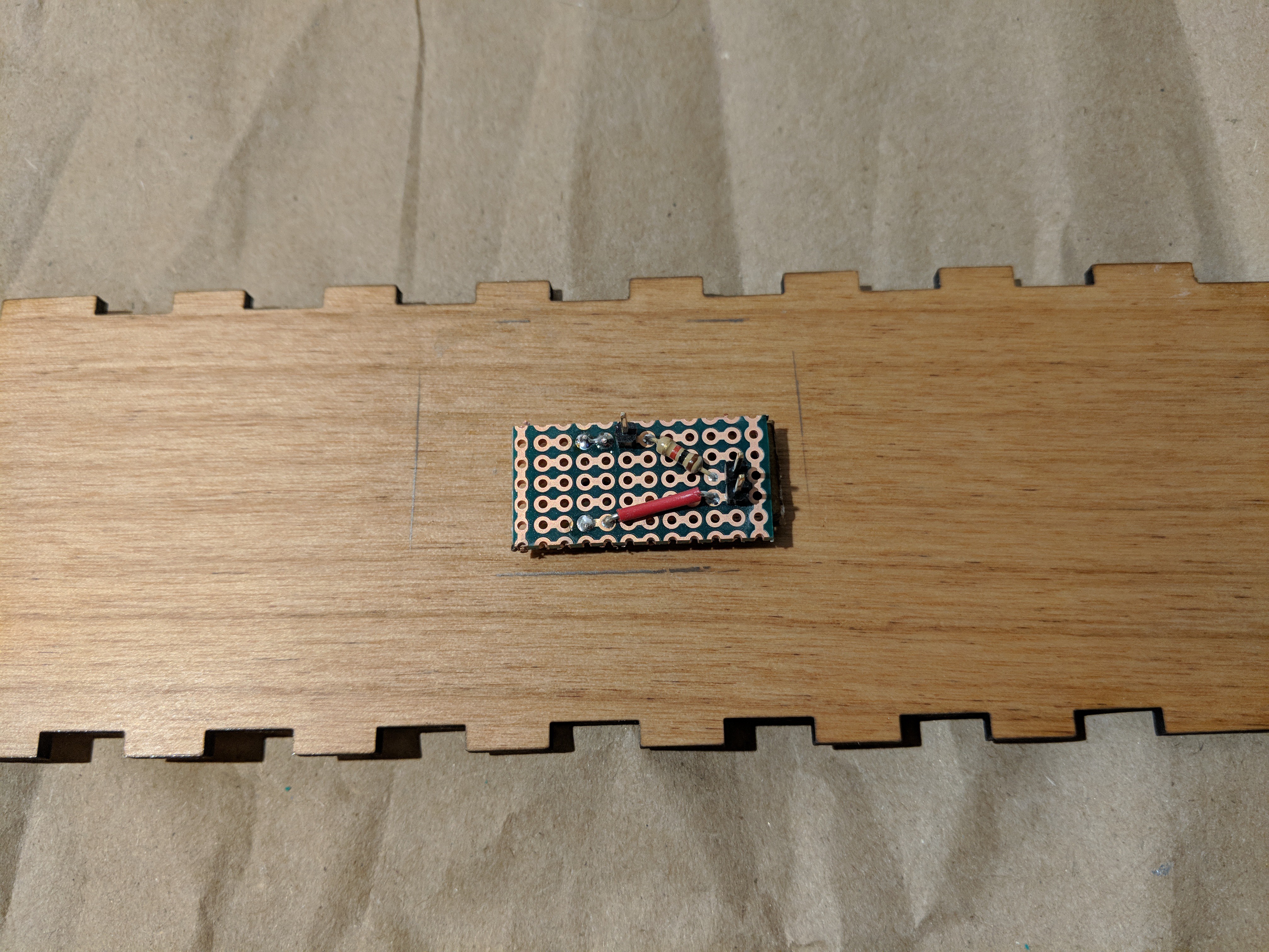
If you look around the small board there, you can see a pencil outline that represents the footprint of that board before I took the Dremel to it. I did that after realizing that interior space was very tight, and things were not going to fit unless I accounted for insets on both the front and the back. Whew. Bullet dodged.
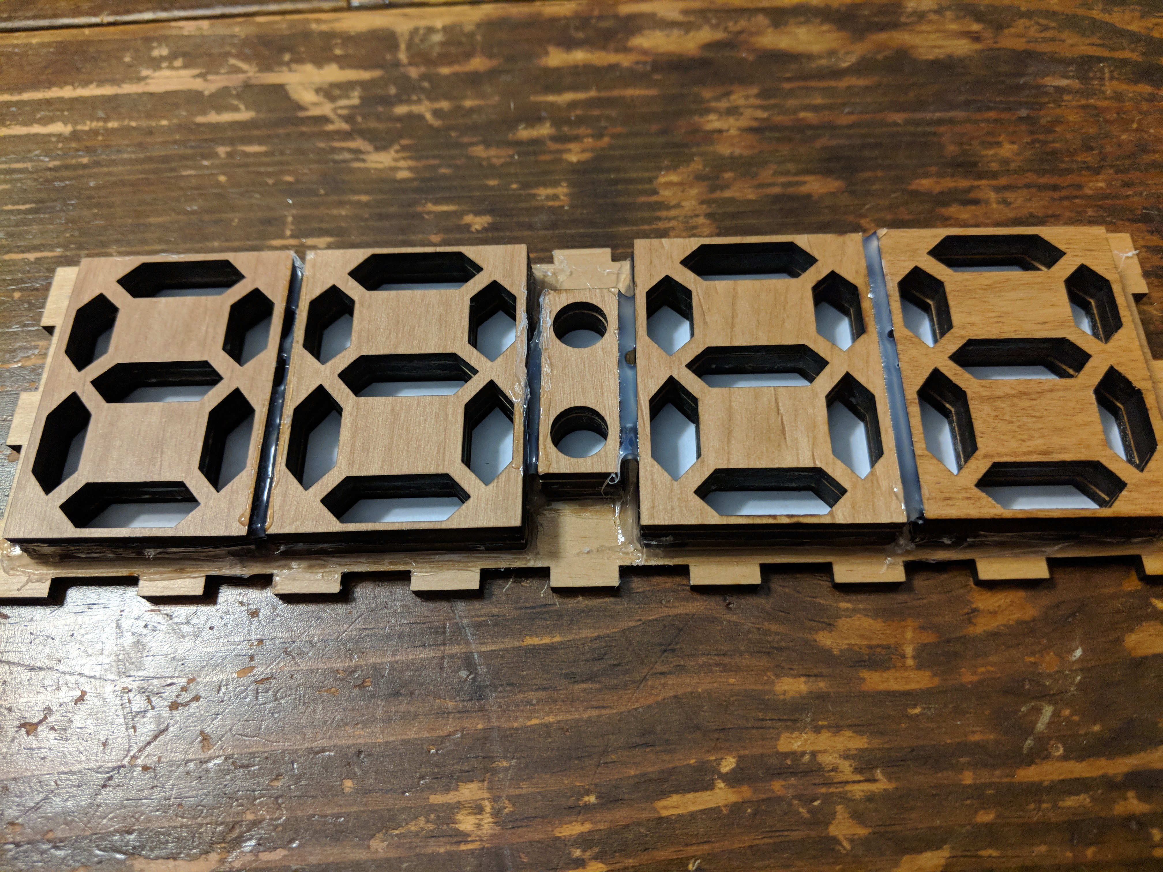
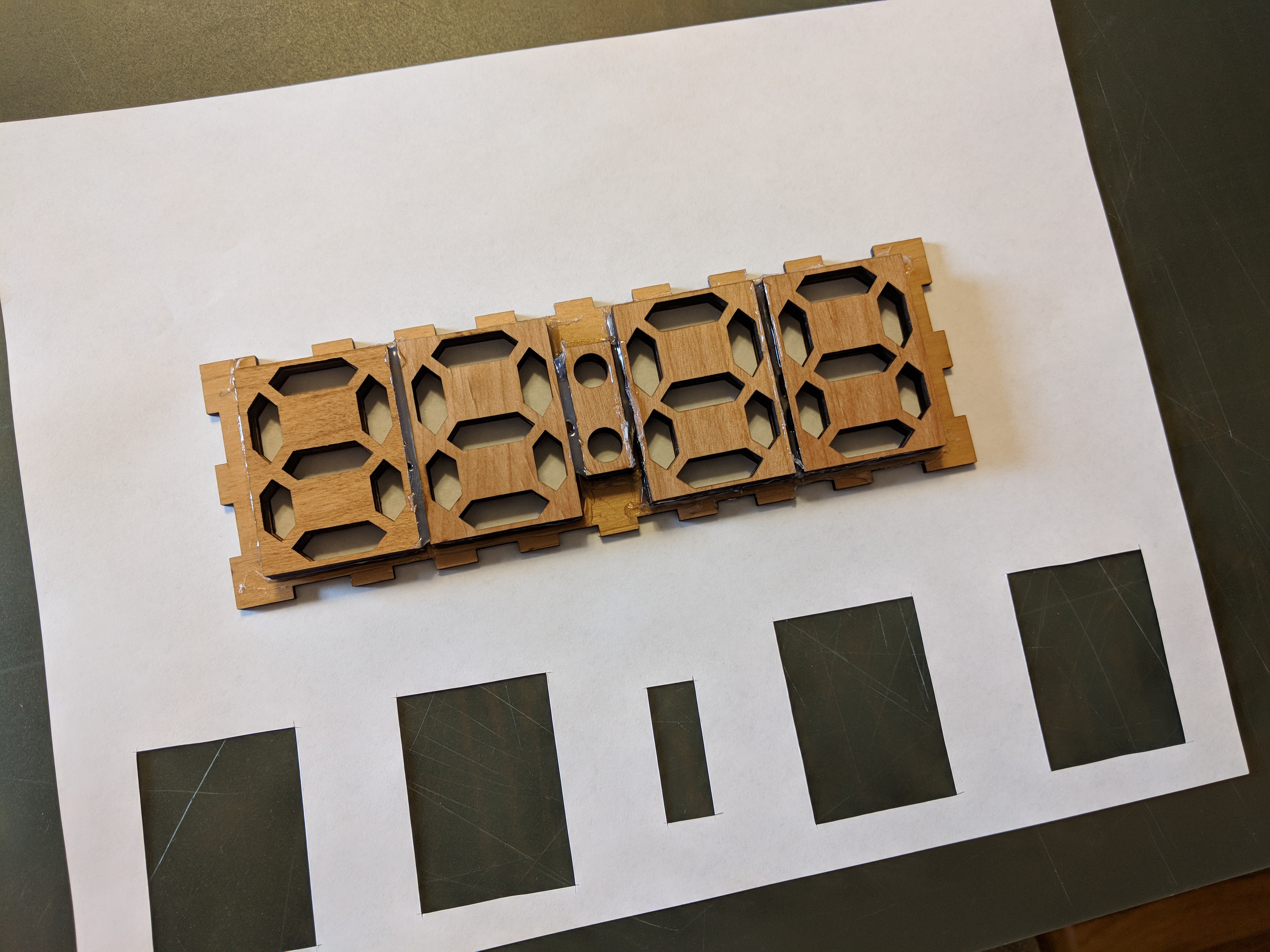
Next, I turned my attention to the digits. The digit segment shrouds are made of three 3mm layers of wood, stacked and glued together. Since abandoning my initial plans for a 3D printed enclosure, I've been moving forward with a plan for wood + paper. The thin white paper acts as a diffuser for the light for each segment.
All of my experiments had been considering digits in isolation, so I went ahead and glued (with Elmers glue stick) paper to the front of all my digit pieces. When dry, I used an X-Acto knife to cut them free along their outlines.


Now it was time to get these affixed to the inside front face of the clock. Because I didn't really plan ahead with through-holes for all of these mountings, it was back to the hot glue. To make sure that I was getting the segment openings lined up well, I traced the digit shroud outlines onto the faceplate interior before covering them in paper.

Not super pretty, but not terrible! Using a plastic collar stay to smooth down the glue and force it into the corners was fairly effective. But wait, what's this...
I should have been extremely pleased with this result, but I wasn't. This wasn't going to give me the look I was hoping for. The contrast of the white paper with the wood is great, but the segments stand too much. Even with some of the segments lit in a color, the unlit white segments were going to be too visually distracting to be an effective clock. This was when I realized that what I really wanted was a smooth, featureless front. My experiments with 3D printed front-faces has this, and so did my individual digit tests with paper. So, now I just needed to figure out how to get that look across the whole front.
If I was going to cover the whole face of the clock in paper, have it stick, and not look stained, I was going to need a new weapon.
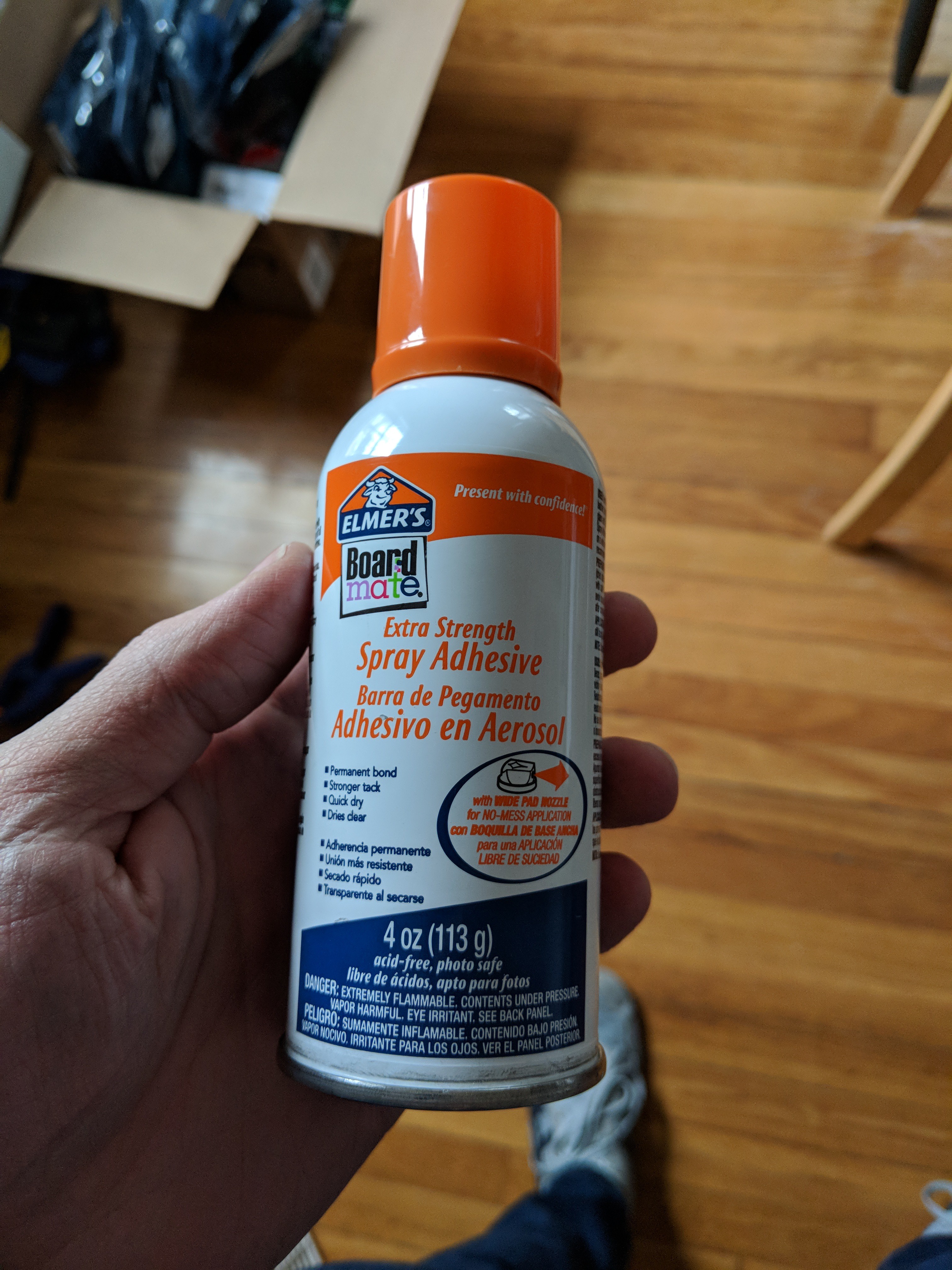
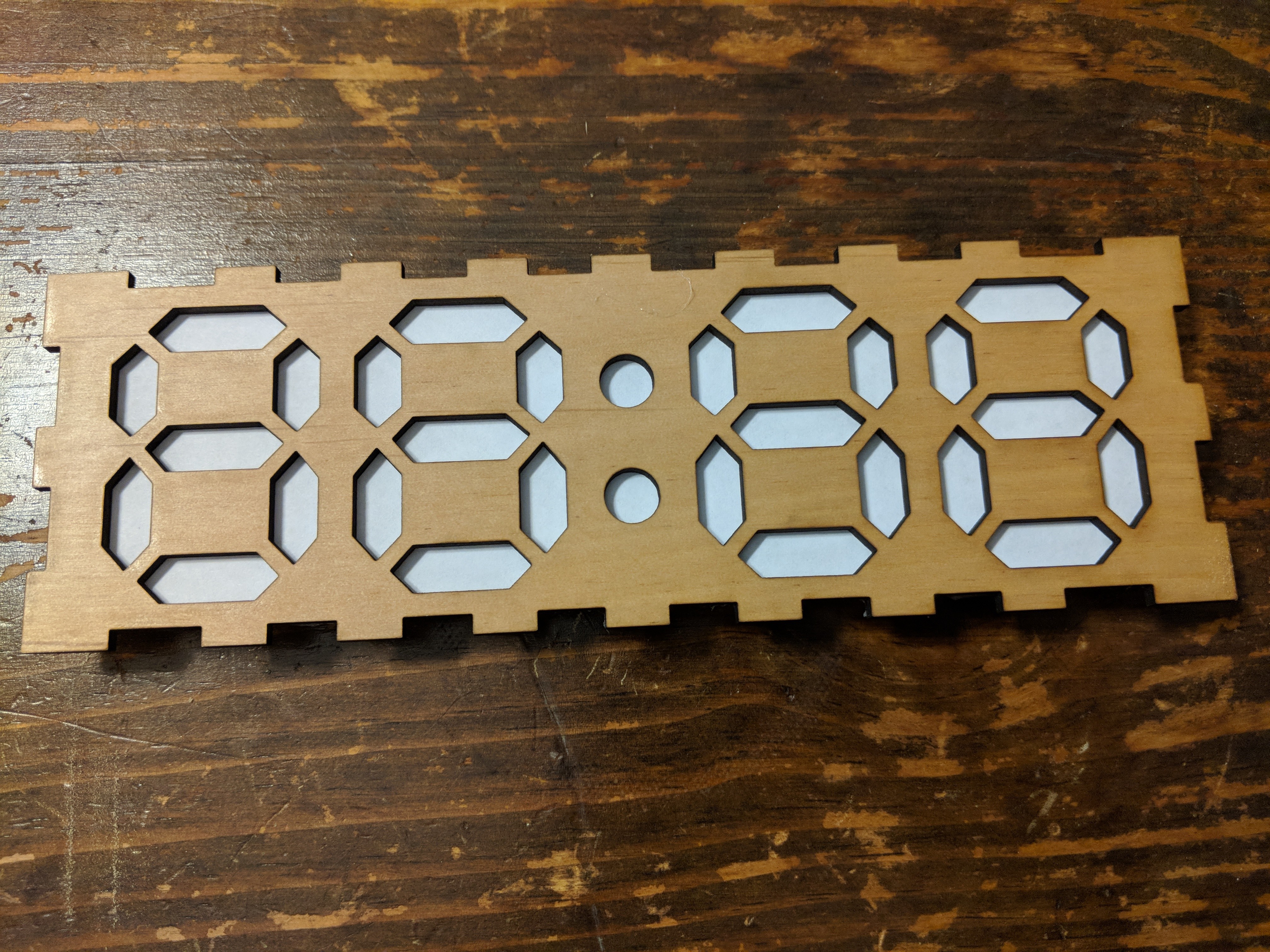
After coating the exterior face of the clock with spray adhesive (sorry, individual paper segments!), I pressed it back onto my paper, and set it to dry under the pressure of some heavy books. A little while later, I grabbed my X-Acto again and traced the significantly more complex outline of the faceplate, cutting it away from the sheet.
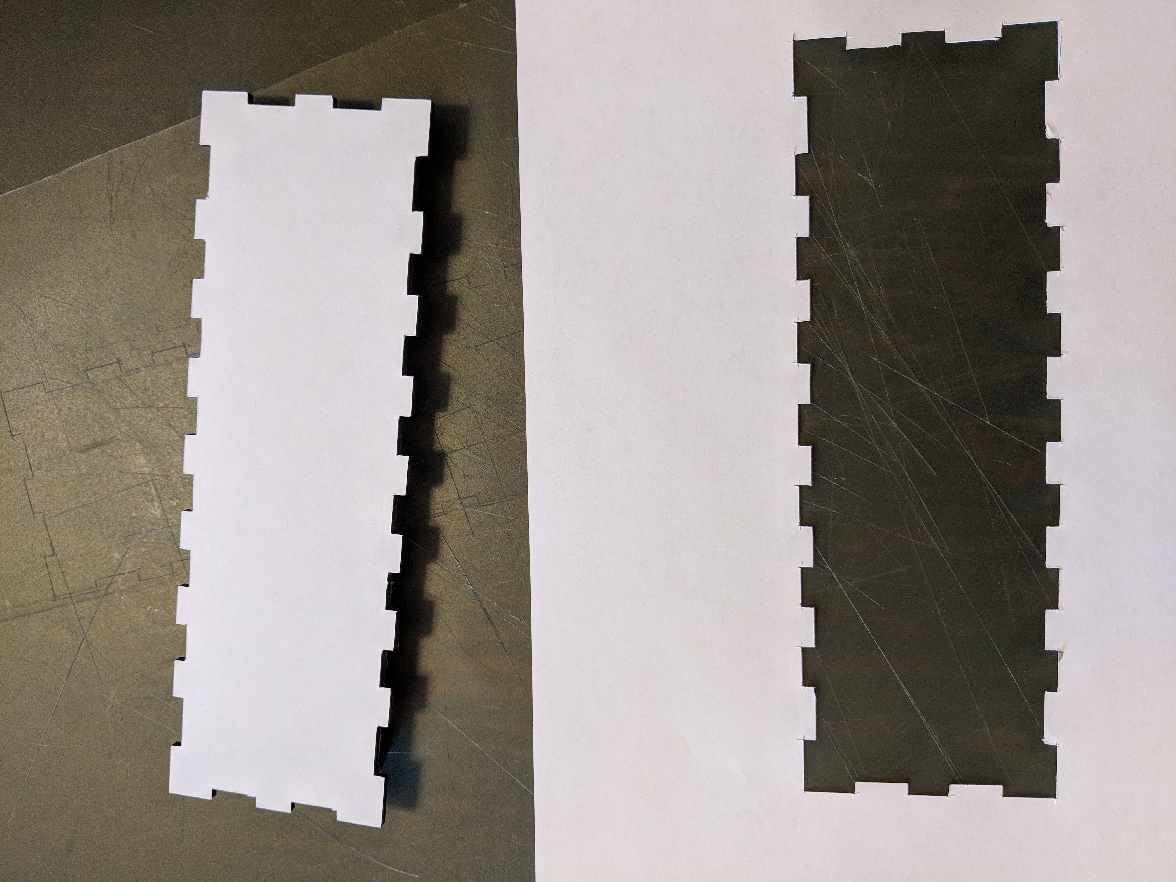
Nice! The spray adhesive worked great, and all of my corners stayed well attached.
With that, the faceplate is ready to receive some digit PCBs. Fire up the hot glue gun!
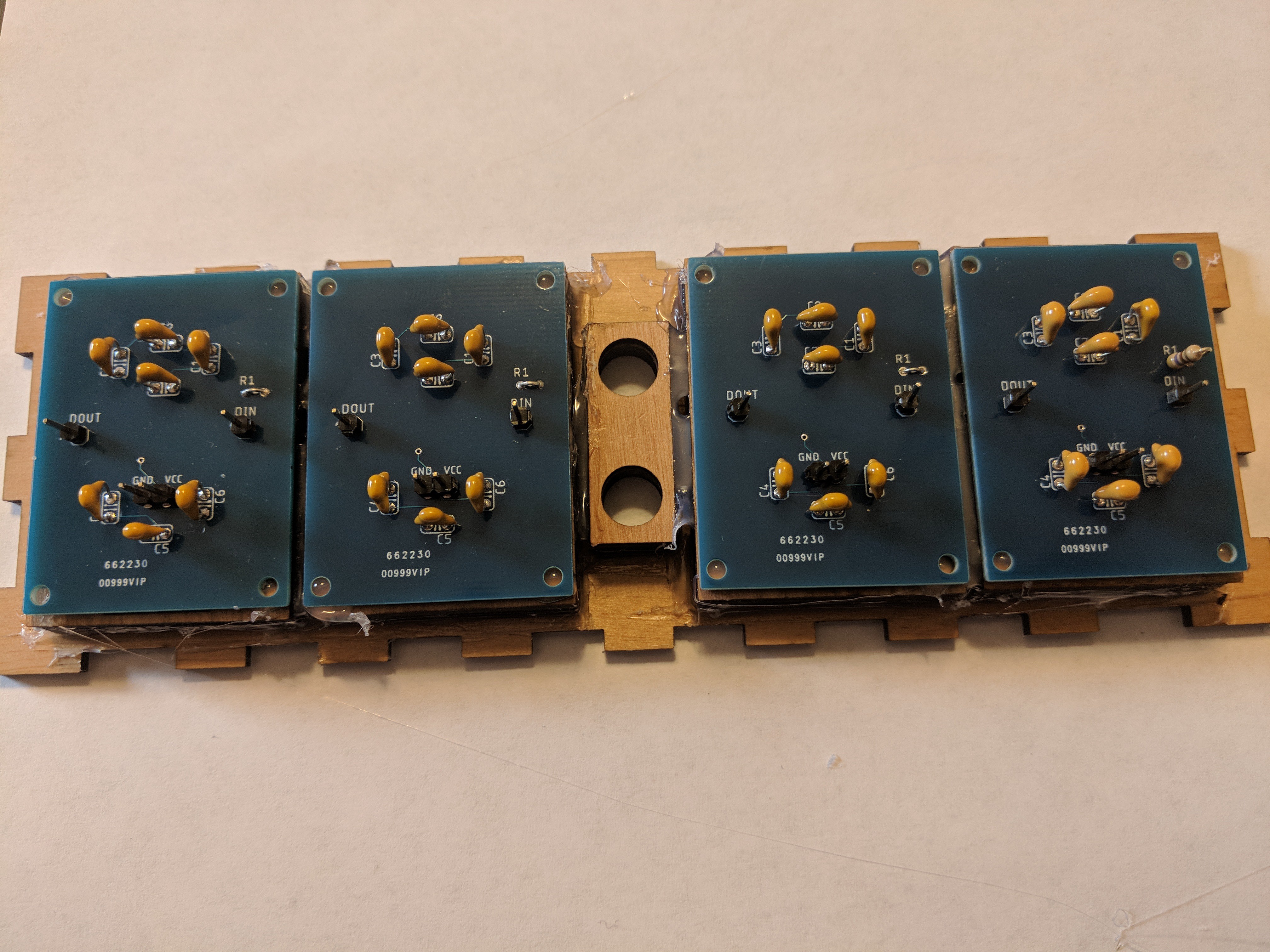
A little dab in every corner got the job done nicely. I hope I don't ever need to get these boards back off! Now, let's see how it's looking...

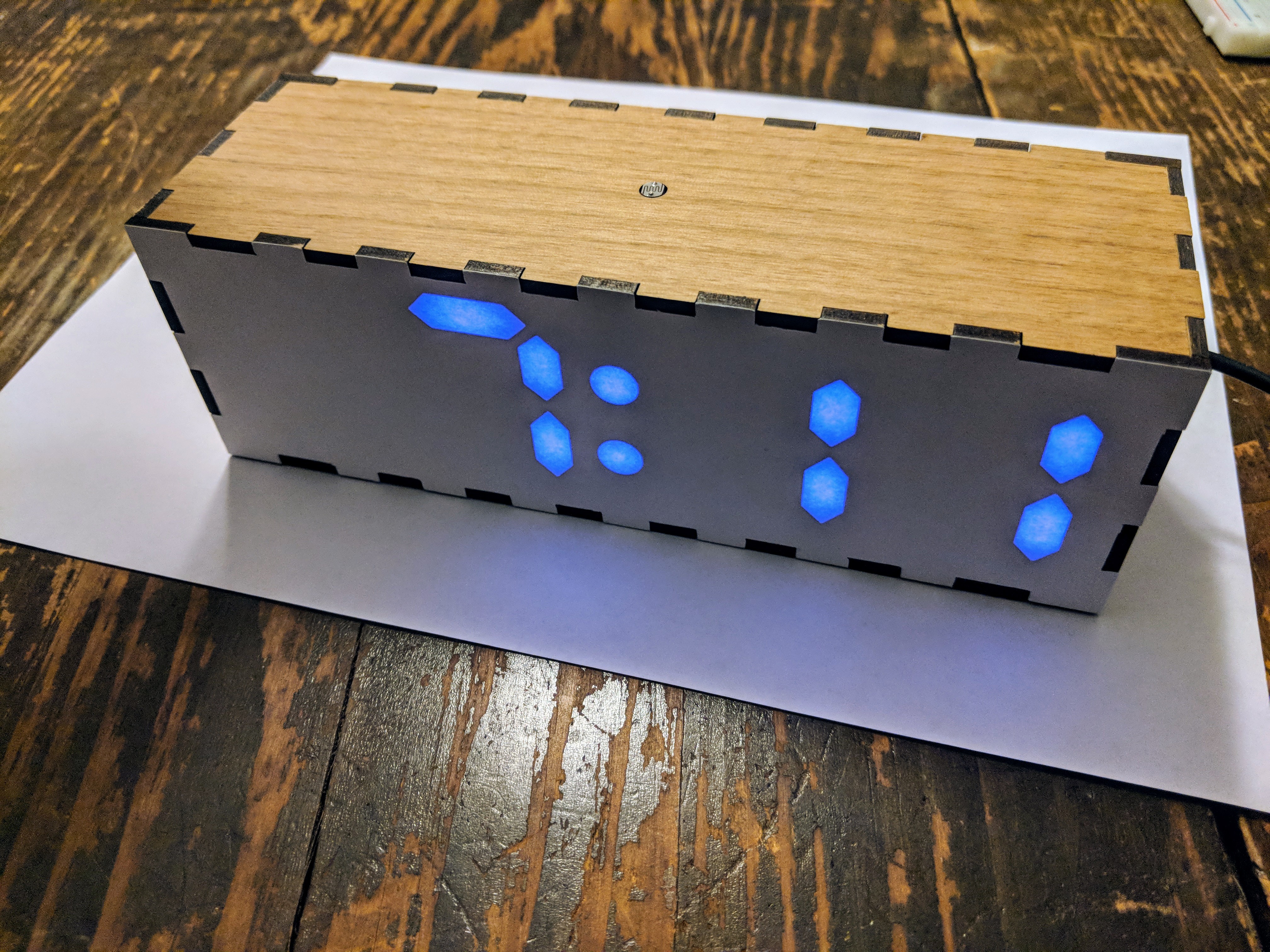
Heck yeah. Nice color, clean crisp segment lines, no distraction from the segments that are off. It just looks like the paper itself is glowing! Let's bring it home...
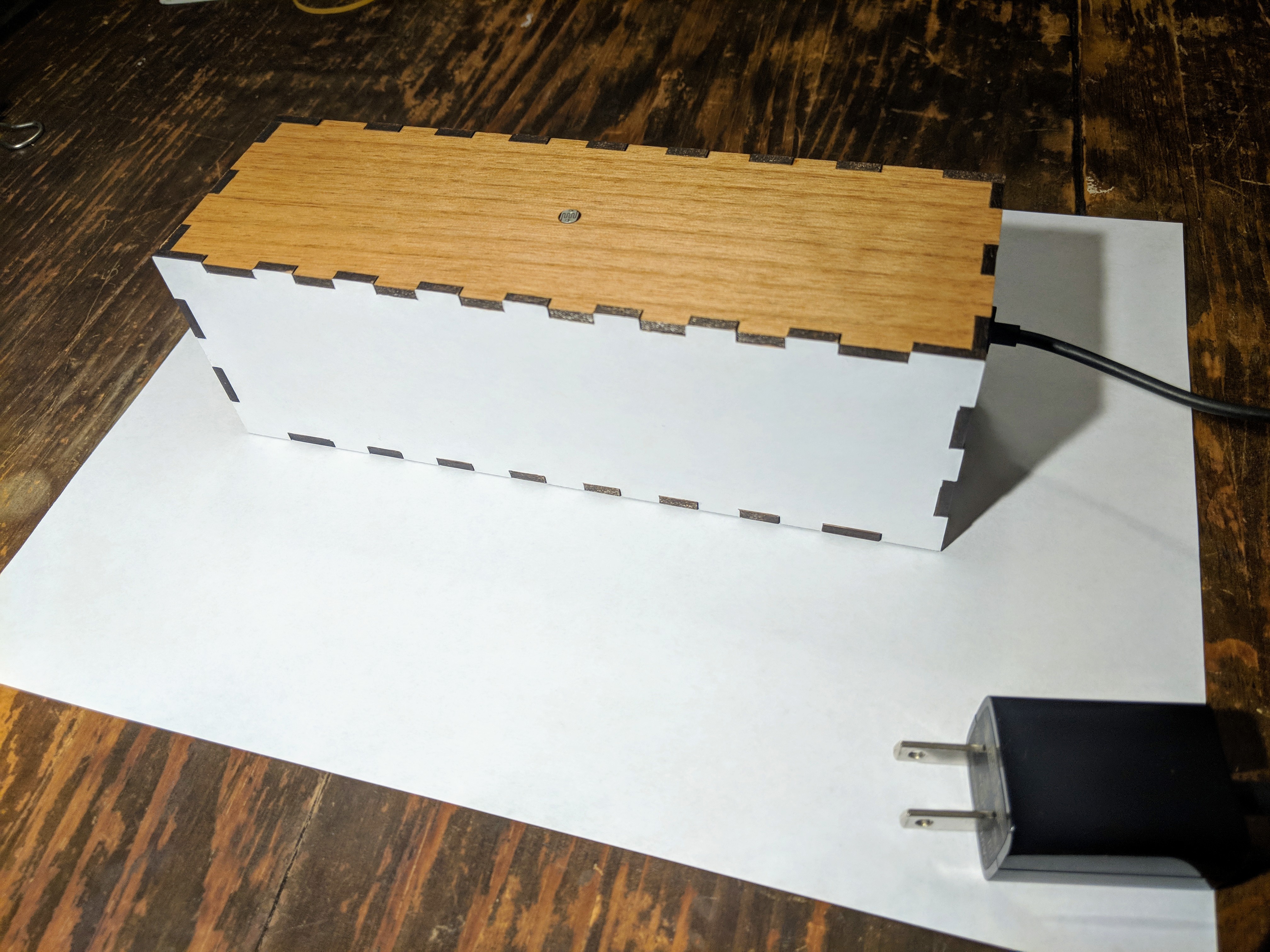
I brought the box together with some light sanding on all the tabs followed by wood glue on all the interlocking surfaces. The clamps were probably overkill, but made me feel cool.
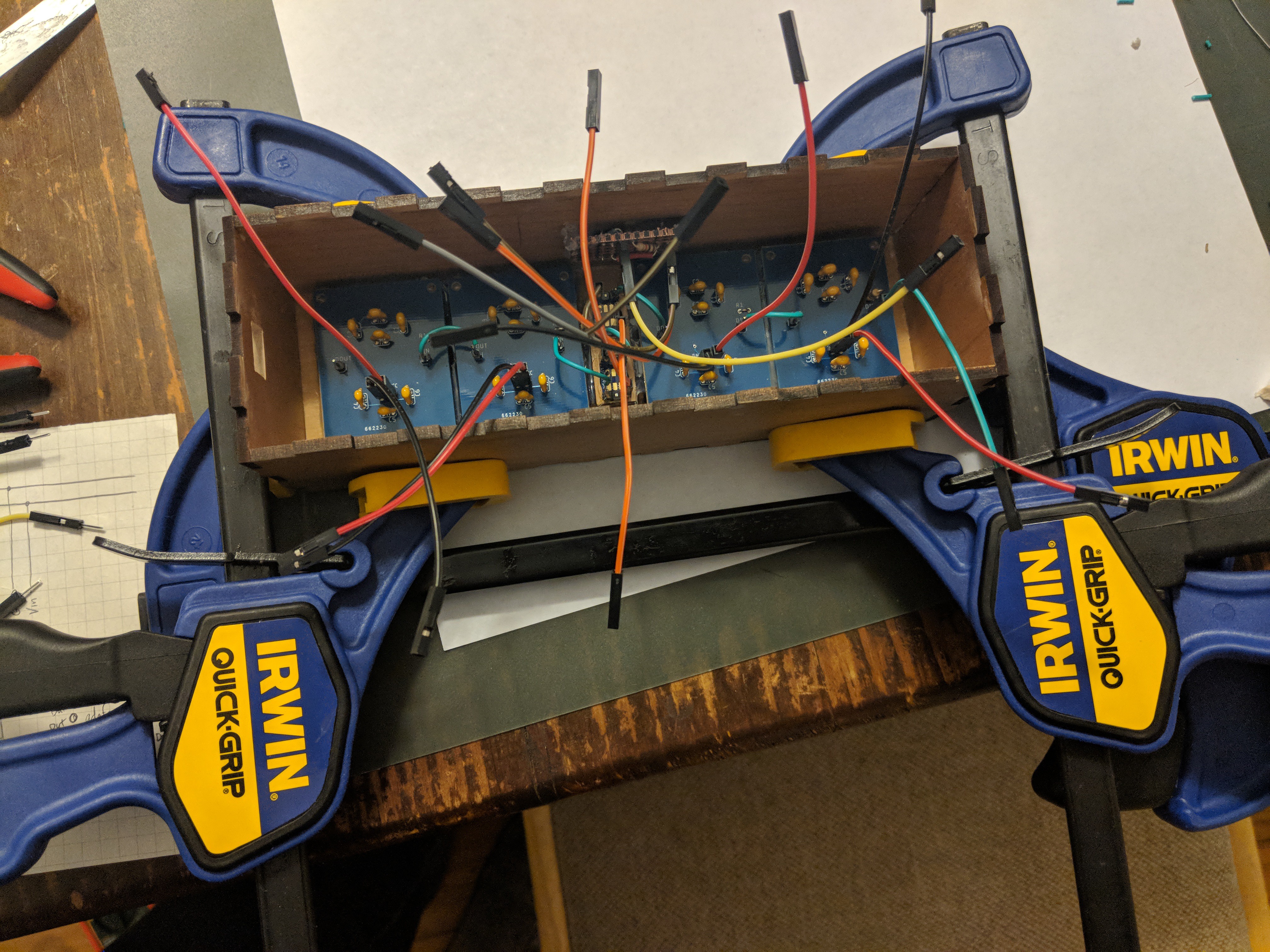
The one last side holds all the rest of the electronics, which I tried to make as compact as possible by removing the header connectors and soldering the wires directly for any connections that were contained to that side.
Careful connecting of all the interior wires, a 5V micro USB charger and cable completes the picture, and there you have it!
Looking back, I've learned a ton while working on this project. Before this, I hadn't done any surface mount soldering. These were only the second PCBs I've ever designed and had printed, and they're the first I've used for something real. This was also my first experience with 3D printing and laser cutting/engraving. Wow! That's a lot of stuff for a little over one month, and it sure was exciting.
Thanks for checking out the NeoPixel Clock Mini!
Discussions
Become a Hackaday.io Member
Create an account to leave a comment. Already have an account? Log In.