-
Replacement panel
10/11/2023 at 07:19 • 0 comments![]()
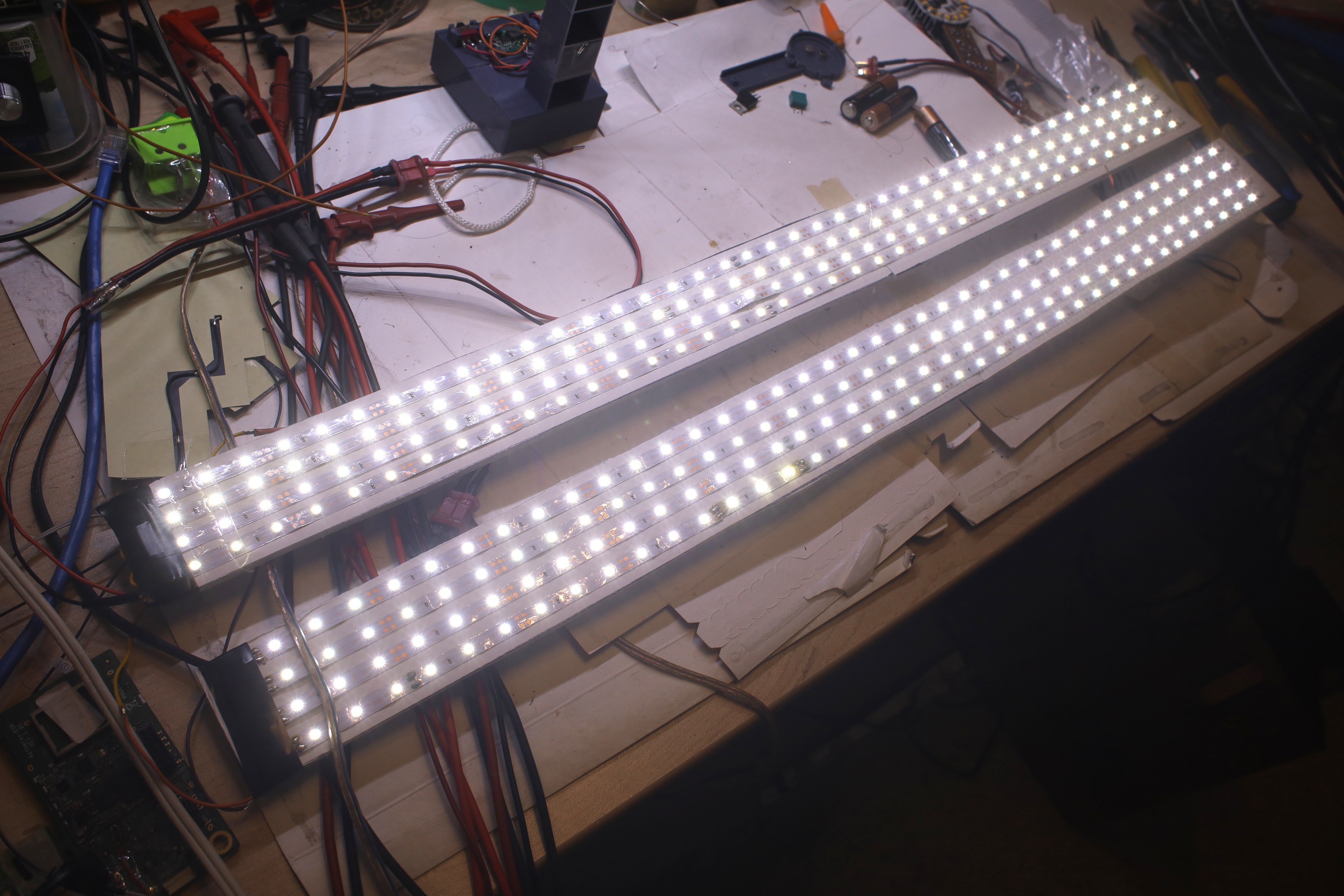
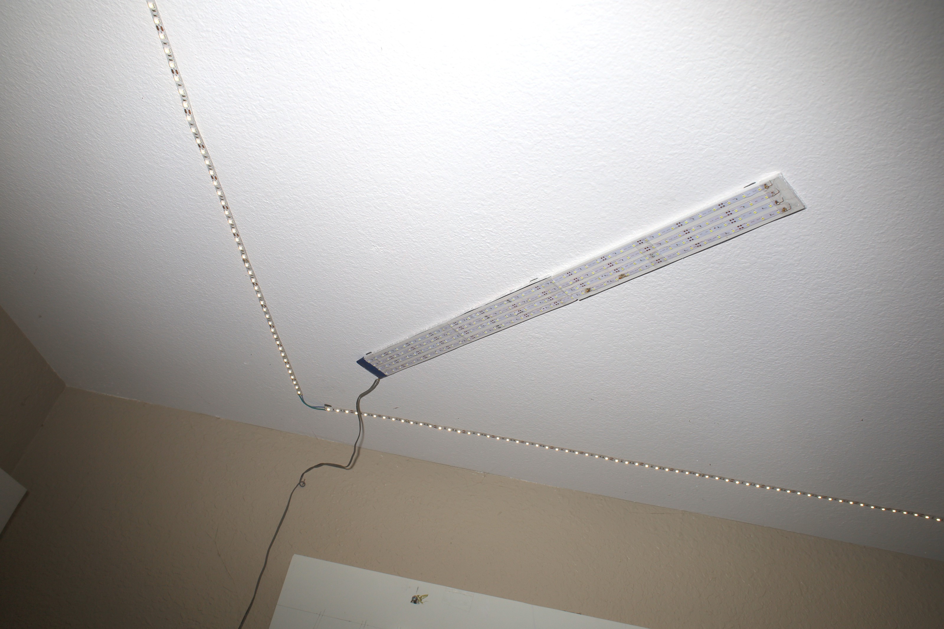
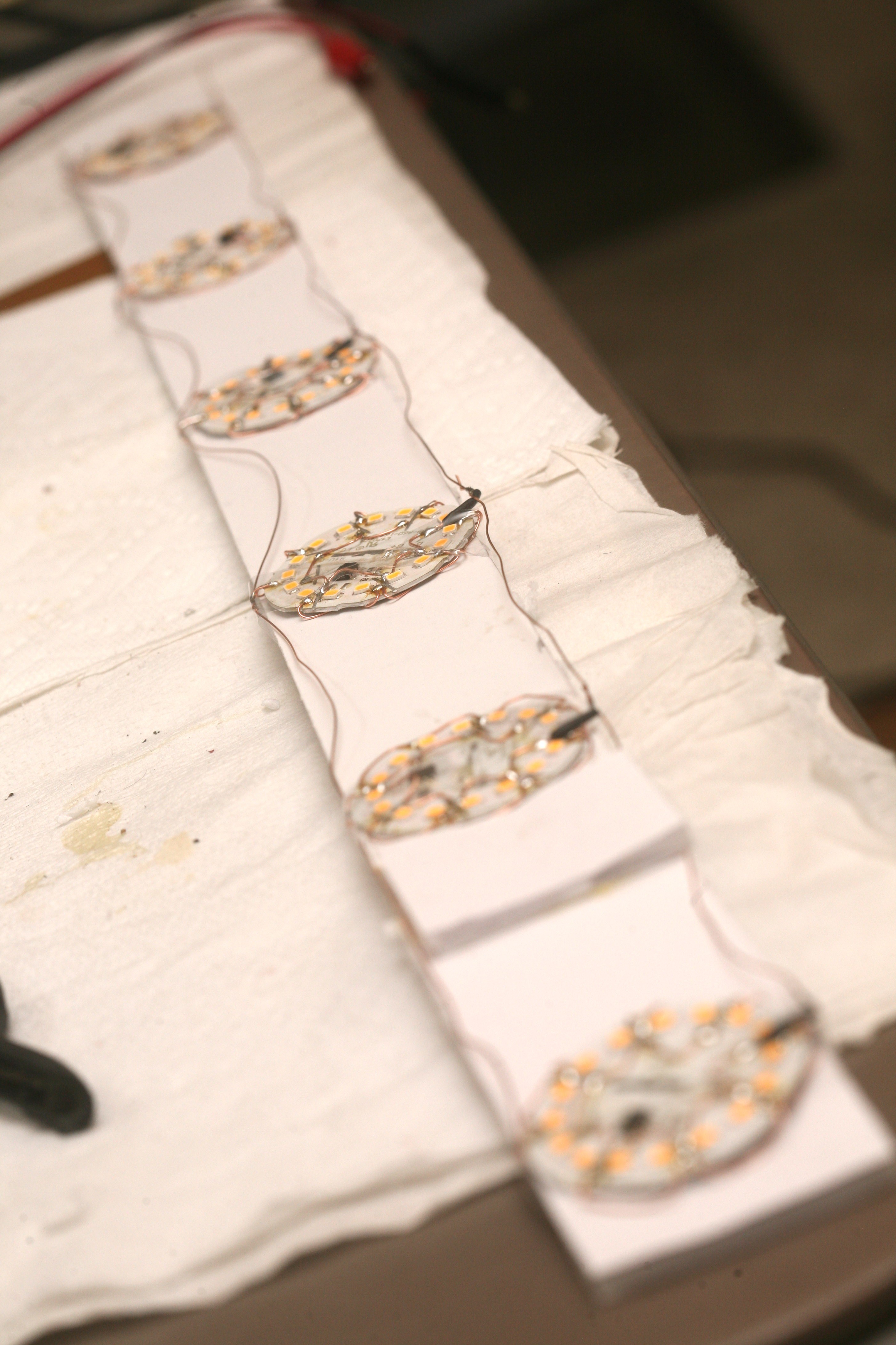
The journey began to replace 1 diagonal & add another diagonal. These dodgy LED strips from bang good already had a few LEDs fail, but all previous lights had dead LEDs since they were made. The decision was made to just burn test them.
These were rated for 12V. They burn .7 - .8A at 11.5V. At 12V, the temperature rises rapidly & the brightness rises just a hair.
![]()
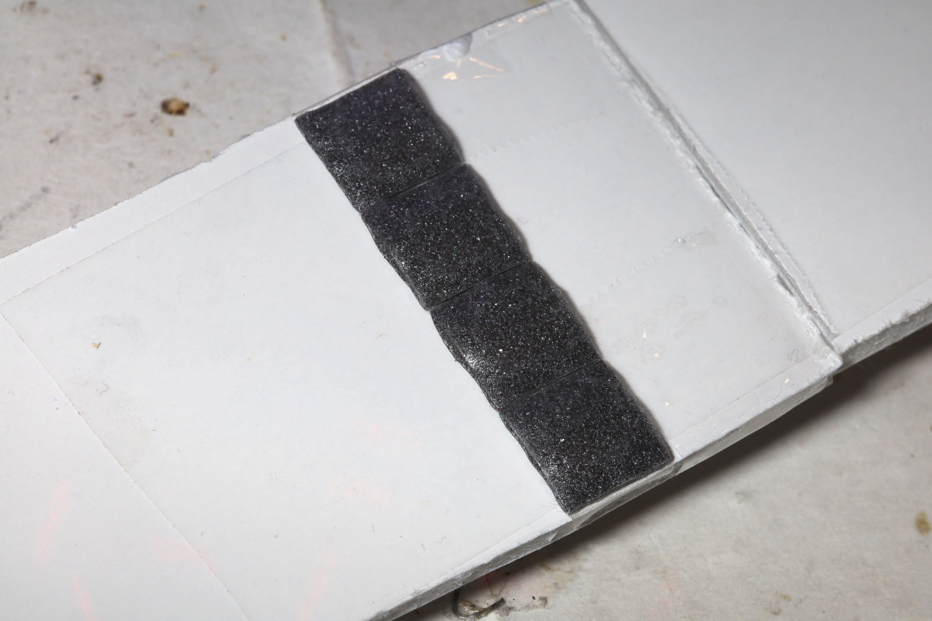
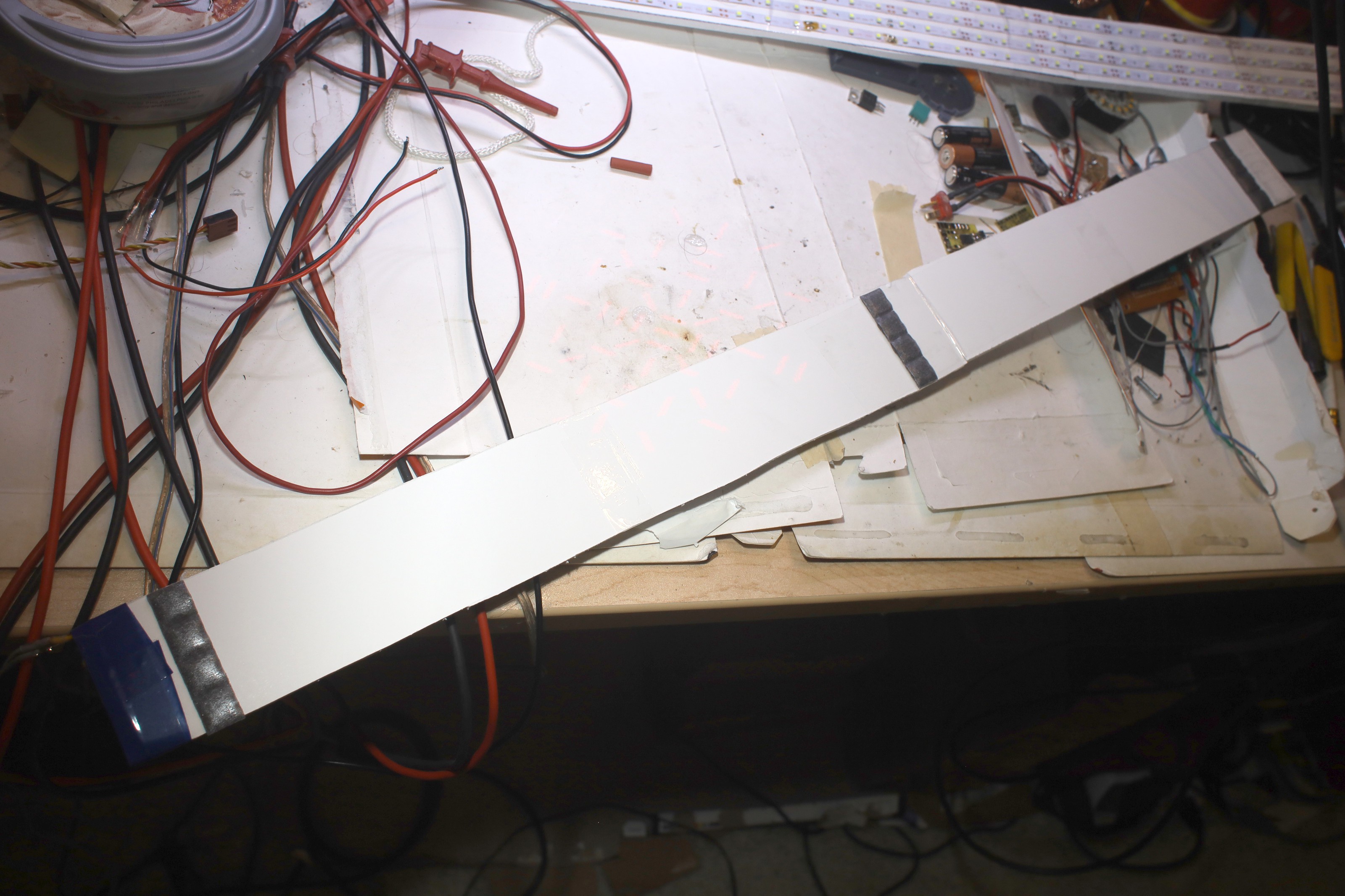
Adhesion of the squares, now $4 per pack, to plastic continues to be a problem. This time, double sided tape was the attempt.
![]()
![]()
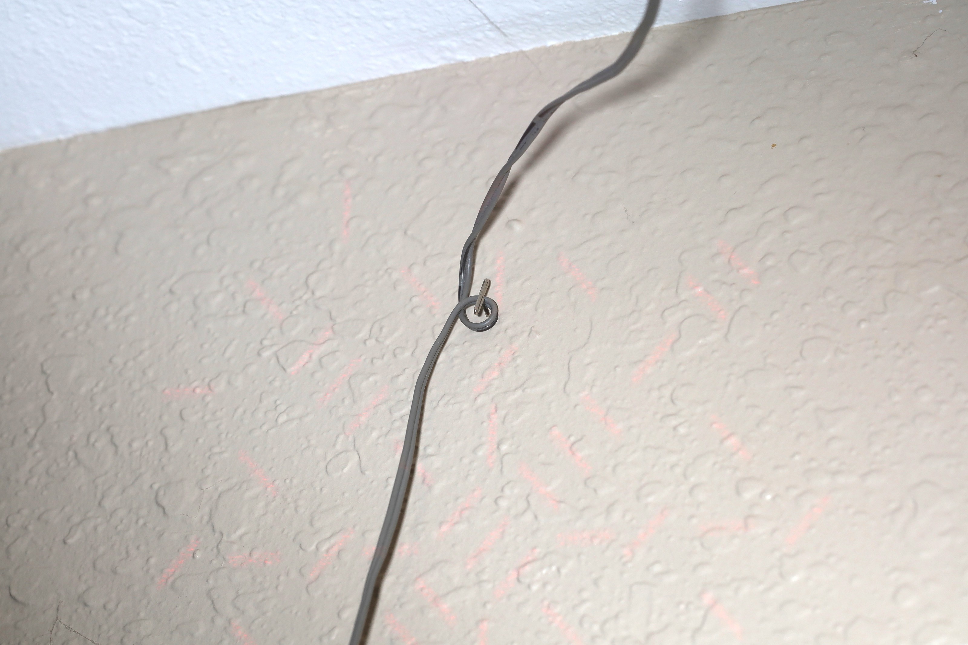
T pins are the new normal way to farsten the cables to the wall.
![]()
![]()
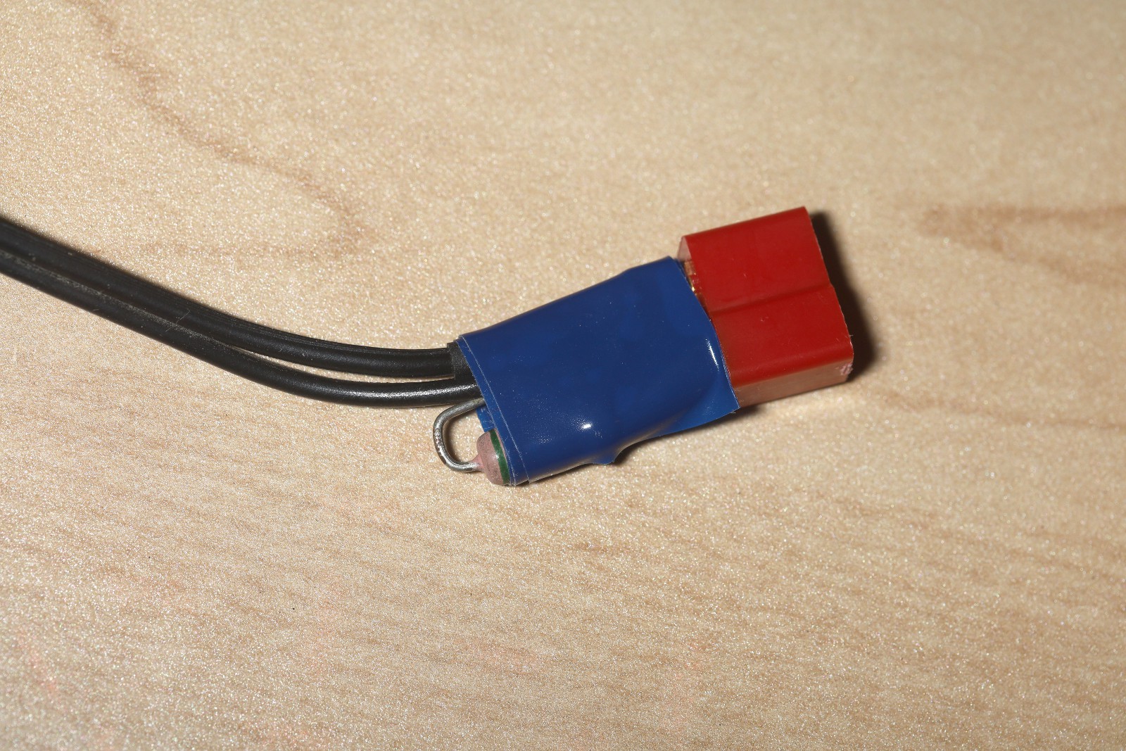
A .55R resistor dropped the 12V to 11.5.
![]()
![]()
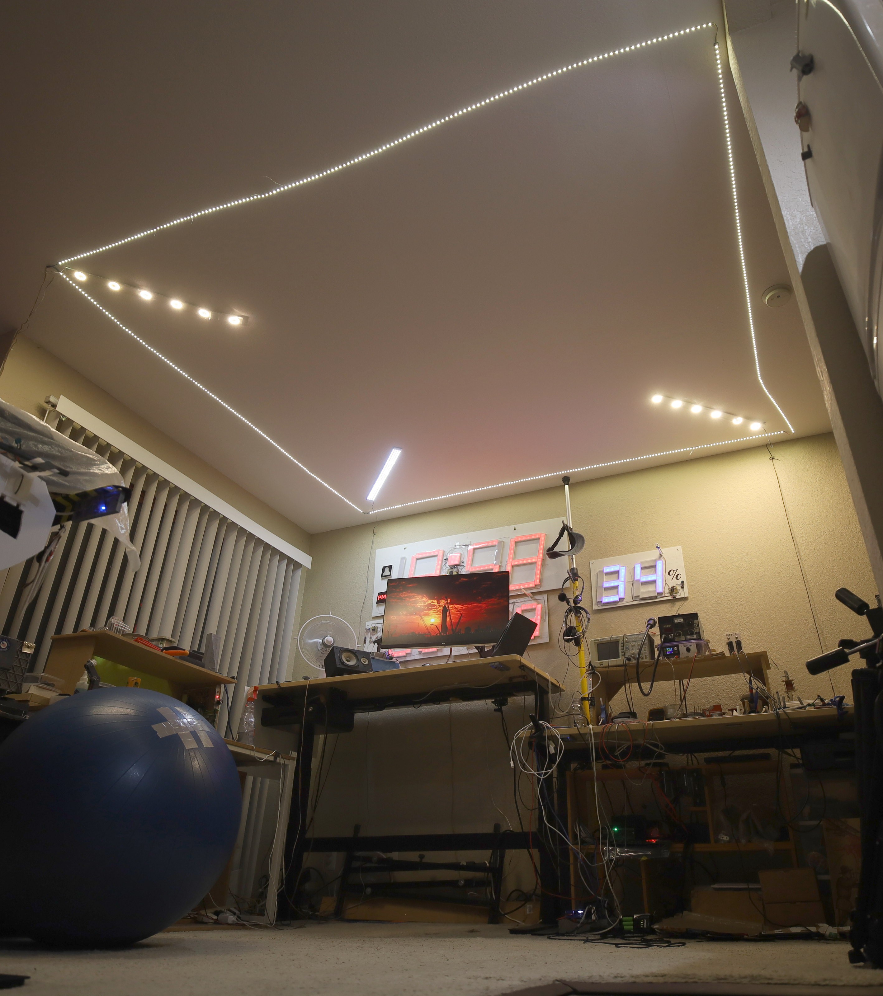
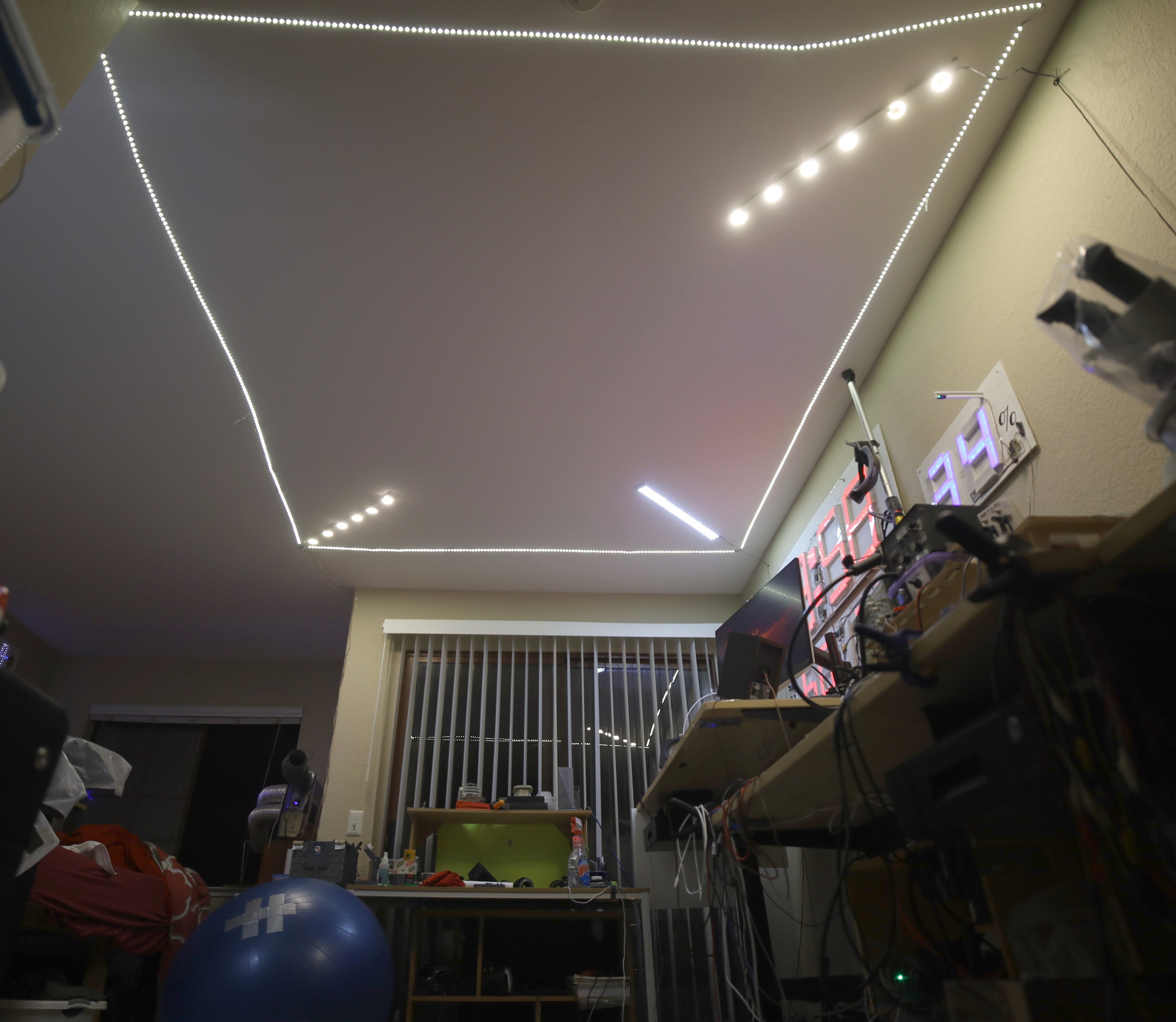
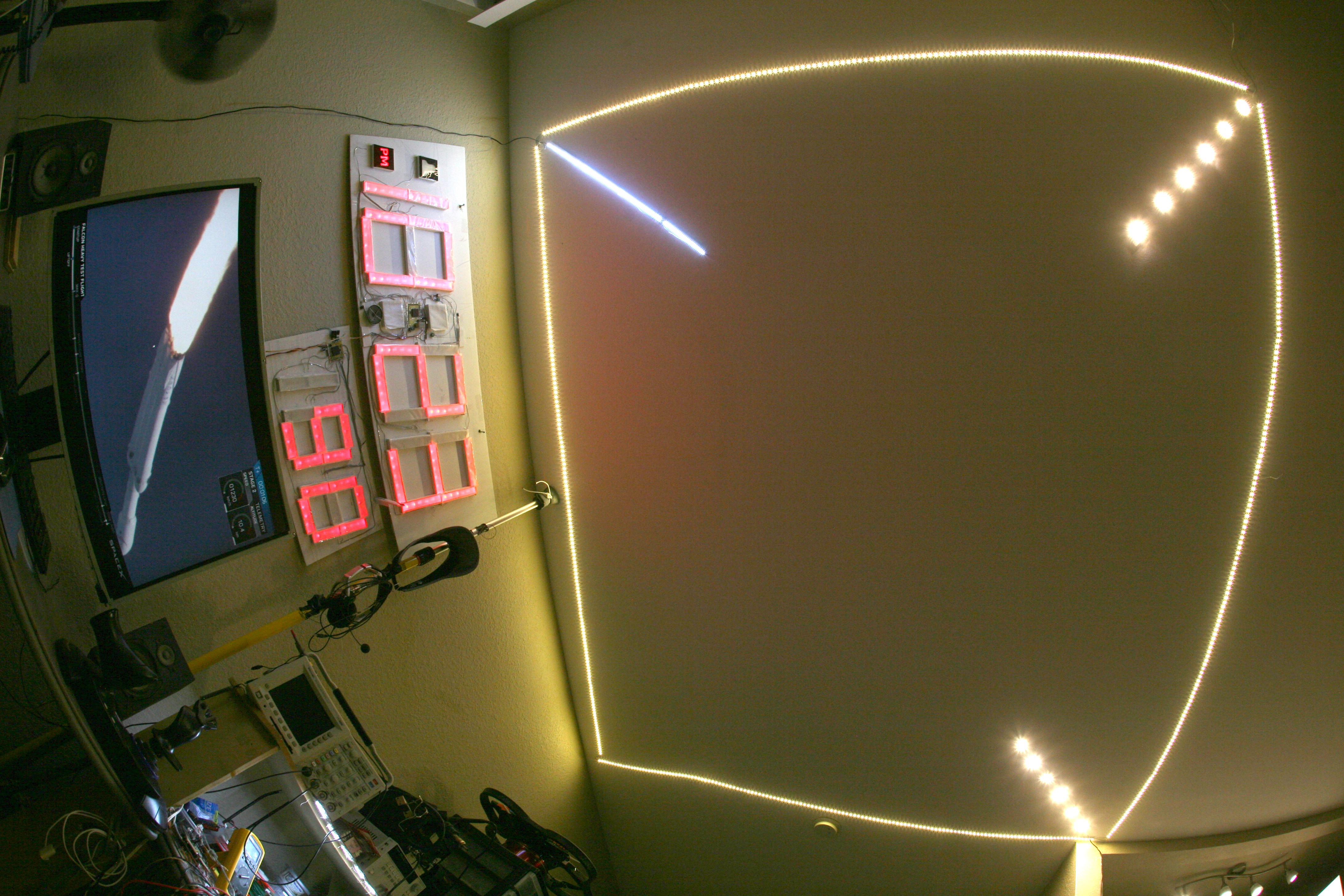
It's exactly where the old one was for 5 years, but much brighter even at 11.5V. The increased brightness might have a glare problem. The LEDs are supposed to gradually fail. They're slightly warmer but still a daylight white.
-
Laptop power supply death
08/29/2022 at 20:10 • 0 commentsAfter 5 years, the 19V laptop brick powering a diagonal strip perished. There is no non destructive way to repair it. There are 2 other laptop bricks, but with similar prospects so swapping one in wasn't worth it.
Thus began conversion to a 3A 12V brick + SEPIC converter to get 16.75. The mane problem with this would be less dropper resistance but lions couldn't afford the wasted heat of the previous solution which used a resistor to drop 19V to 16.75. Helas, the 12V brick had an immediate problem with the inrush current into the SEPIC converter. After many tries with current limiting resistors, it ended up requiring a MOSFET RC circuit to soft start the load.
![]()
The only other time lions built a soft starting circuit was for a microphone switch. They're really temperamental. This one ended up doing the job. The trick is if the light is rapidly turned off & on, it takes a few seconds of off for the soft start to reset enough for the 12V brick.
This led to a desire to move all the diagonal strips to a single 19V power supply & SEPIC converters for each voltage. The 16.75 burns .5A. A long planned future strip will run at 12V.
The square strip began having LEDs die after 5 years.
-------------------------------------------------------------------------------------------------------------------
With the plugs under the tables finally accessible, it was possible to measure the power usage. The ceiling light burns 150W. There is a desire to add more lights. It feels like it could use a variable brightness.
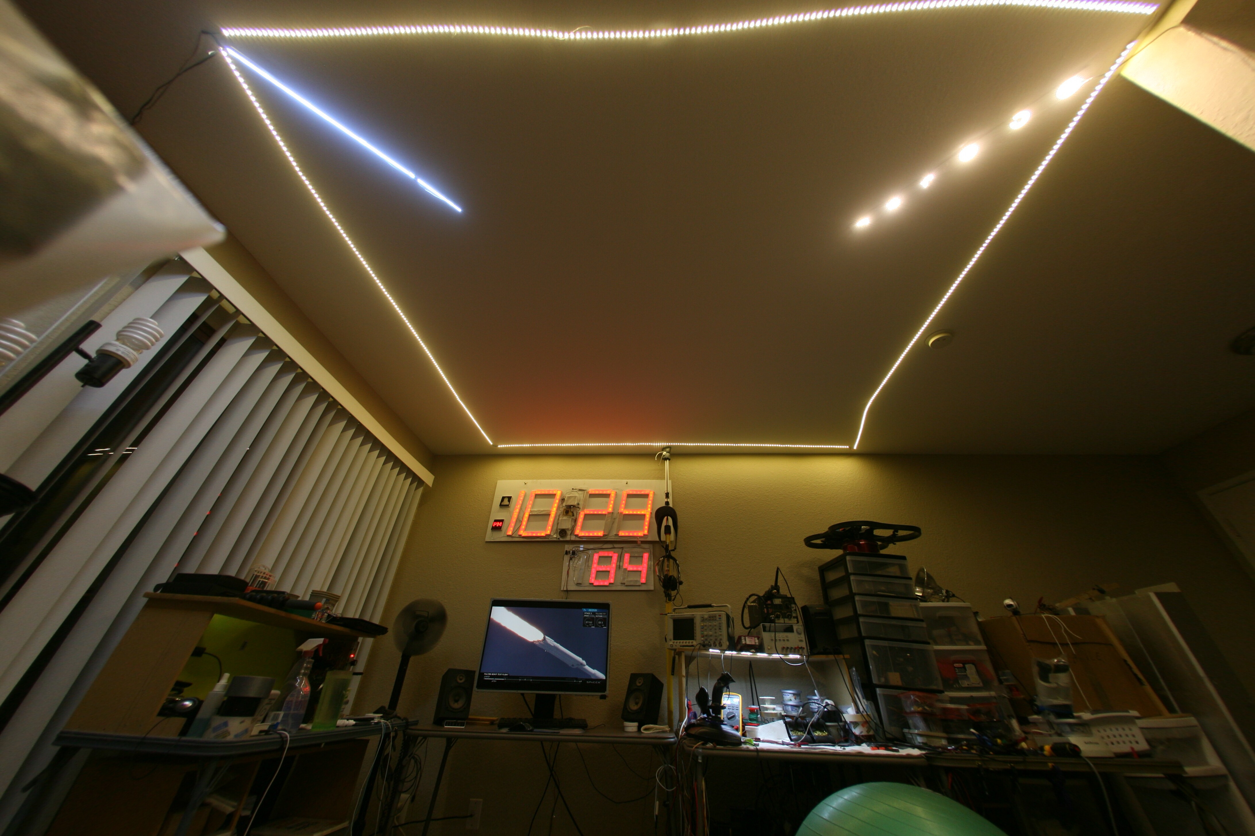
The idea occurred of installing 4 telescoping poles in the corners & creating a frame instead of sticking LEDs on the ceiling. This would take space on the floor, a key regression back to the old days but still not as bad as lamp posts. A metal frame would allow heat dissipation. It would allow more modifications.
Creating the diagonal strips with just 4 poles in the corners would be tricky.
-
1 year later
07/08/2019 at 18:48 • 0 commentsAll the LEDs still worked, after the early failures of some reconstituted 8W bulbs. The mane casualty was the 15V Mean Well power supply. It suddenly went to 0V after the 1st heat wave of the year. Its fan had been removed during the winter because of the noise. Without the fan, during the Summer, its heat sinks were getting to 50C. The hottest parts were the heat sinks & the RF choke rather than the transformer.
Thus, it was proven that the Mean Well needs a fan. It actually came back to life once cooled. It seemed to have a thermal fuse which needed to cool to room temperature to reset.
It was disappointing to find LED strips had not improved in the last year. The 8W bulbs are being made with fewer LEDs of higher voltage. Lions still wire them in series to reduce the rework. The latest ones use 11V per LED, putting series LEDs above laptop power supplies. Lions still avoid running manes voltage in exposed wires on the ceiling, though running 44V to have 4 LEDs in series is tempting.
By spreading purchases over a longer time, it might be possible to build up more LED strips to replace the reconstituted 8W bulbs.
-
Painting a bridge
08/30/2018 at 08:59 • 0 comments![]()
As soon as a new light strip is fabricated, the oldest one starts burning out. Not as easy as changing lightbulbs. The 18V Sunbeams have done pretty well on 16.5V. The older Brichips died.
![]()
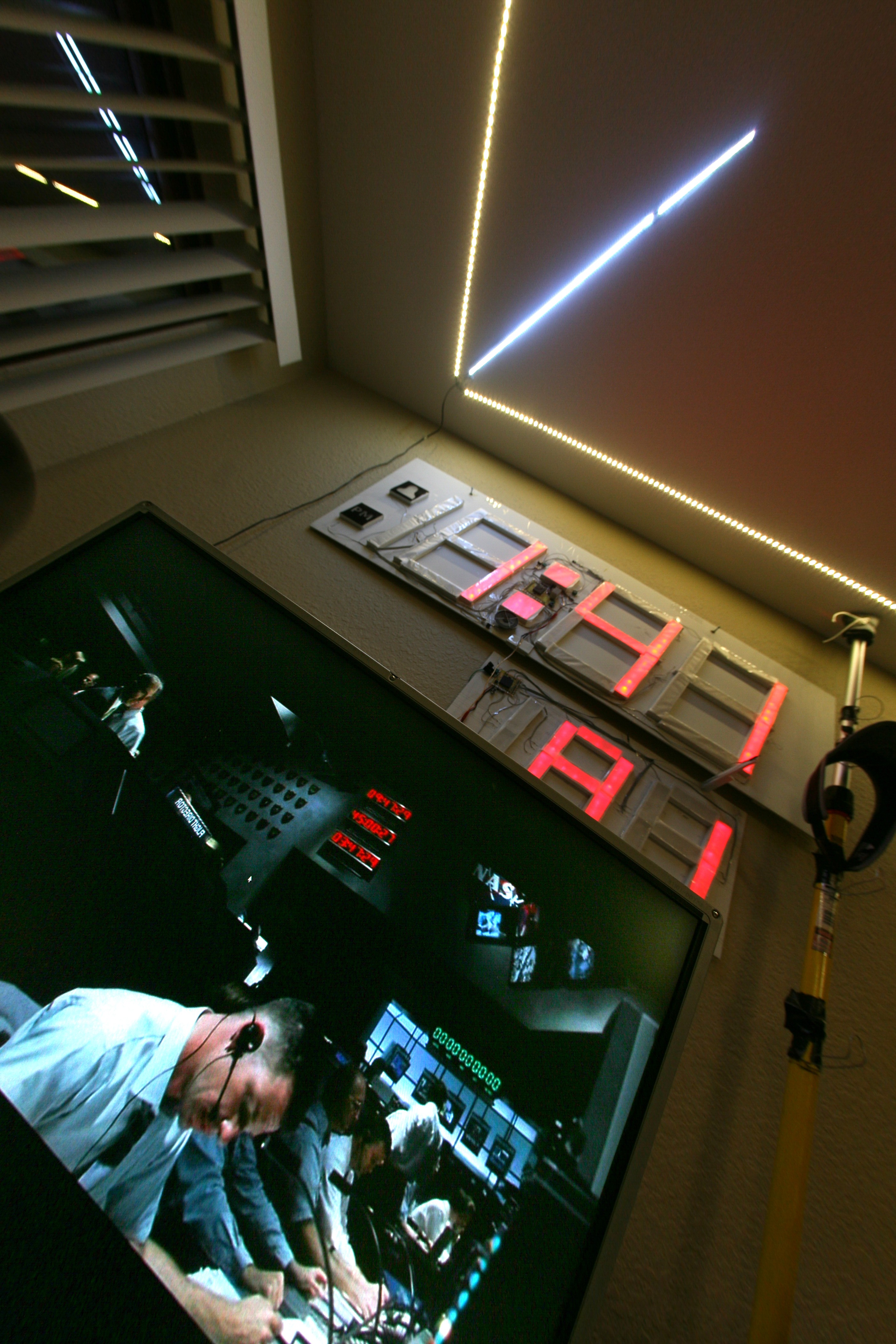
Is it a lion den or a movie?
-
Strip light fabrication
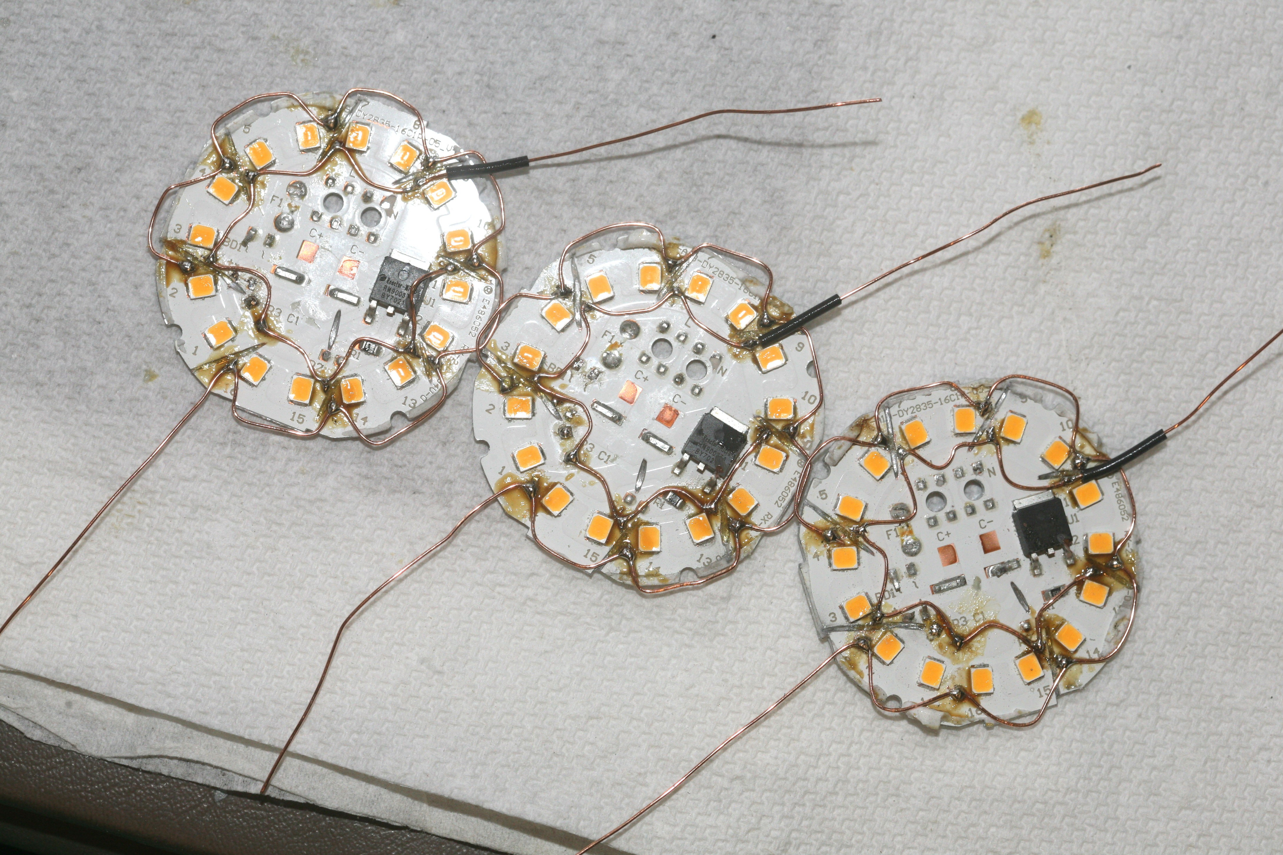
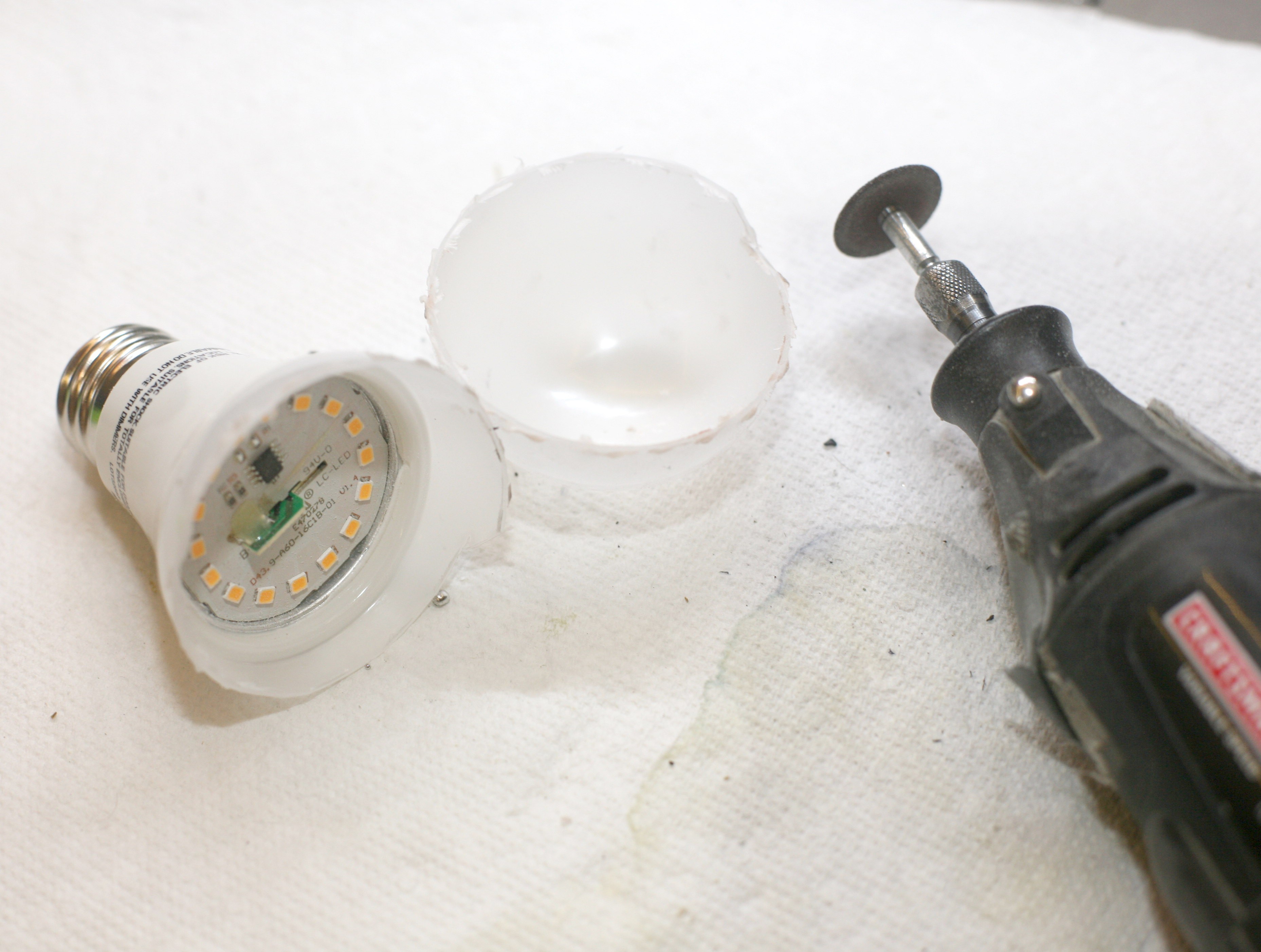
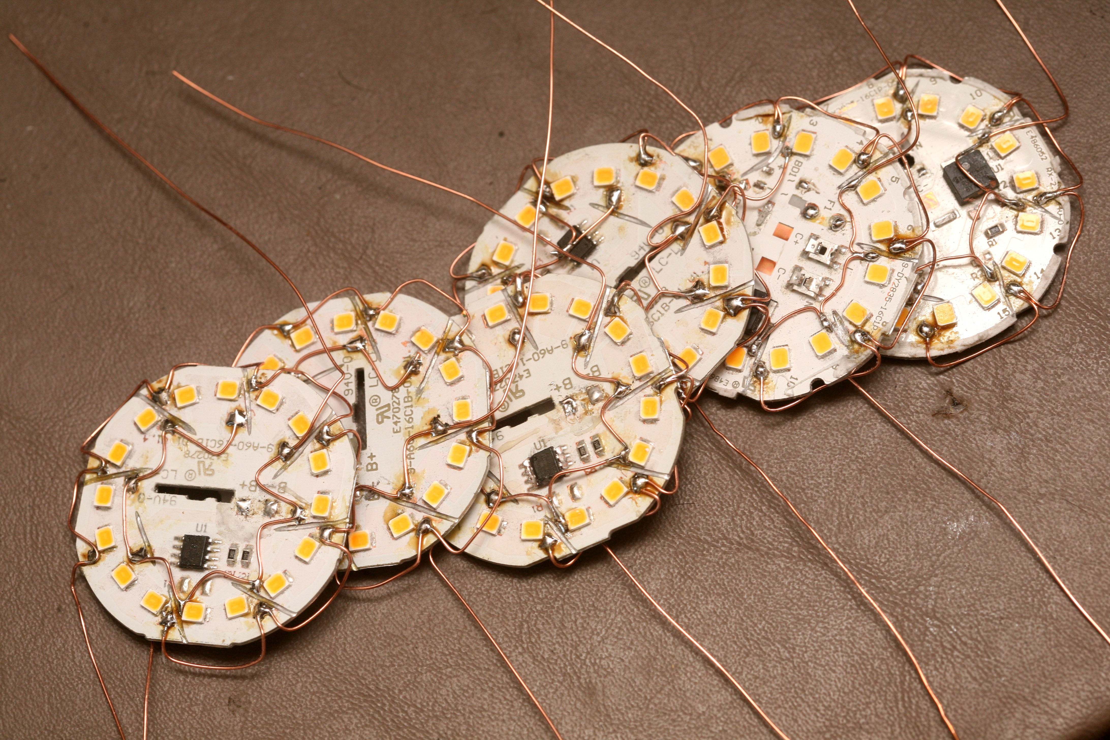
08/18/2018 at 05:30 • 0 commentsThe LED strip lights are so dim, the easiest way to get a truly useful yet adhesive light is smashing hundreds of Sunbeam lightbulbs to make more.
![]()
Those LEDs are driven at 9V when they're cold. Ended up driving pairs at 16V.
![]()
![]()
![]()
Confirmed the LED backlight still works at 9V DC. The PWM mode requires driving them at 3V.
-
15V power
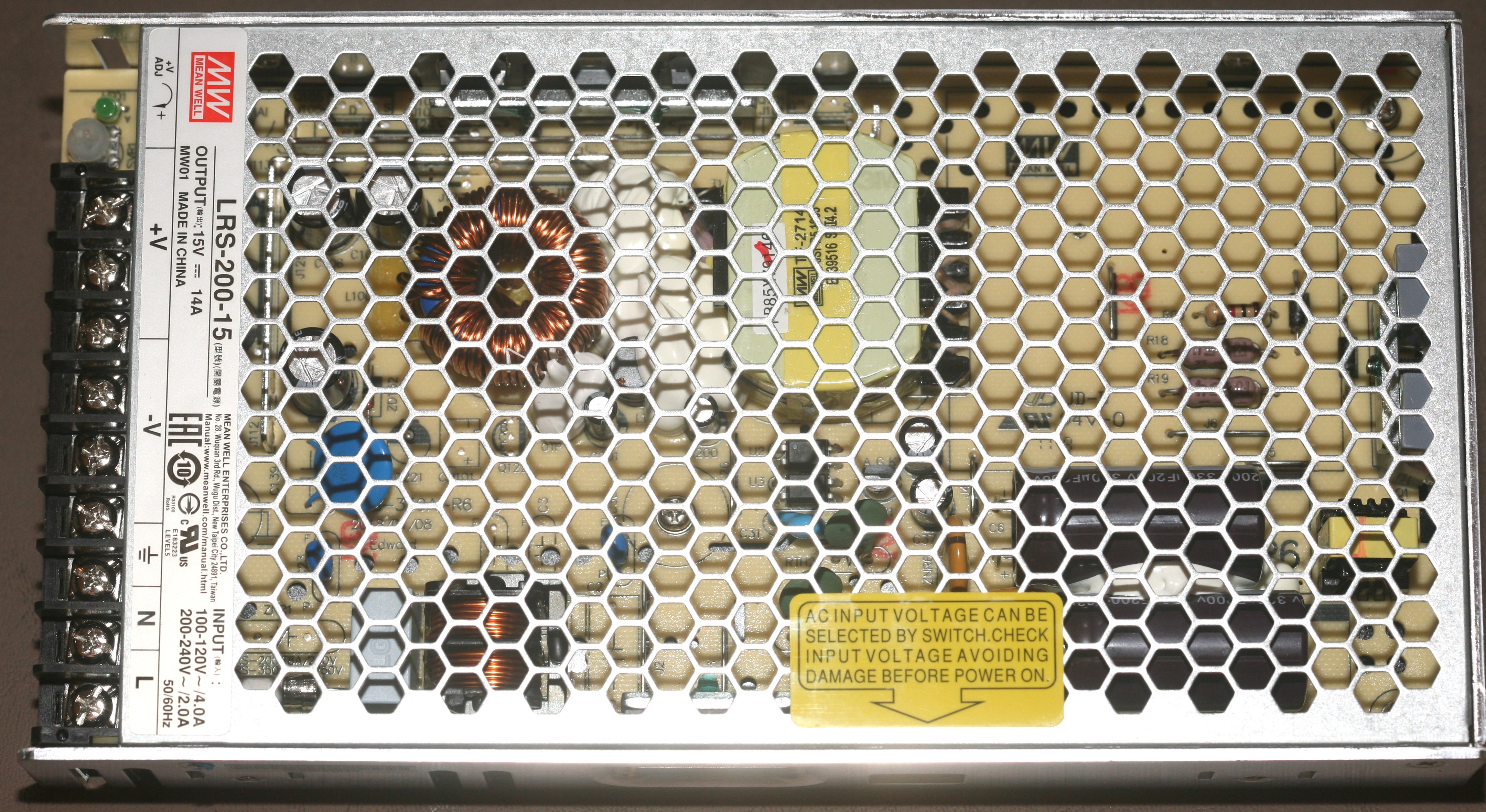
07/31/2018 at 05:38 • 0 commentsAfter 1/2 year of loathing & denial, a dedicated $25 15V 220W supply arrived.
![]()
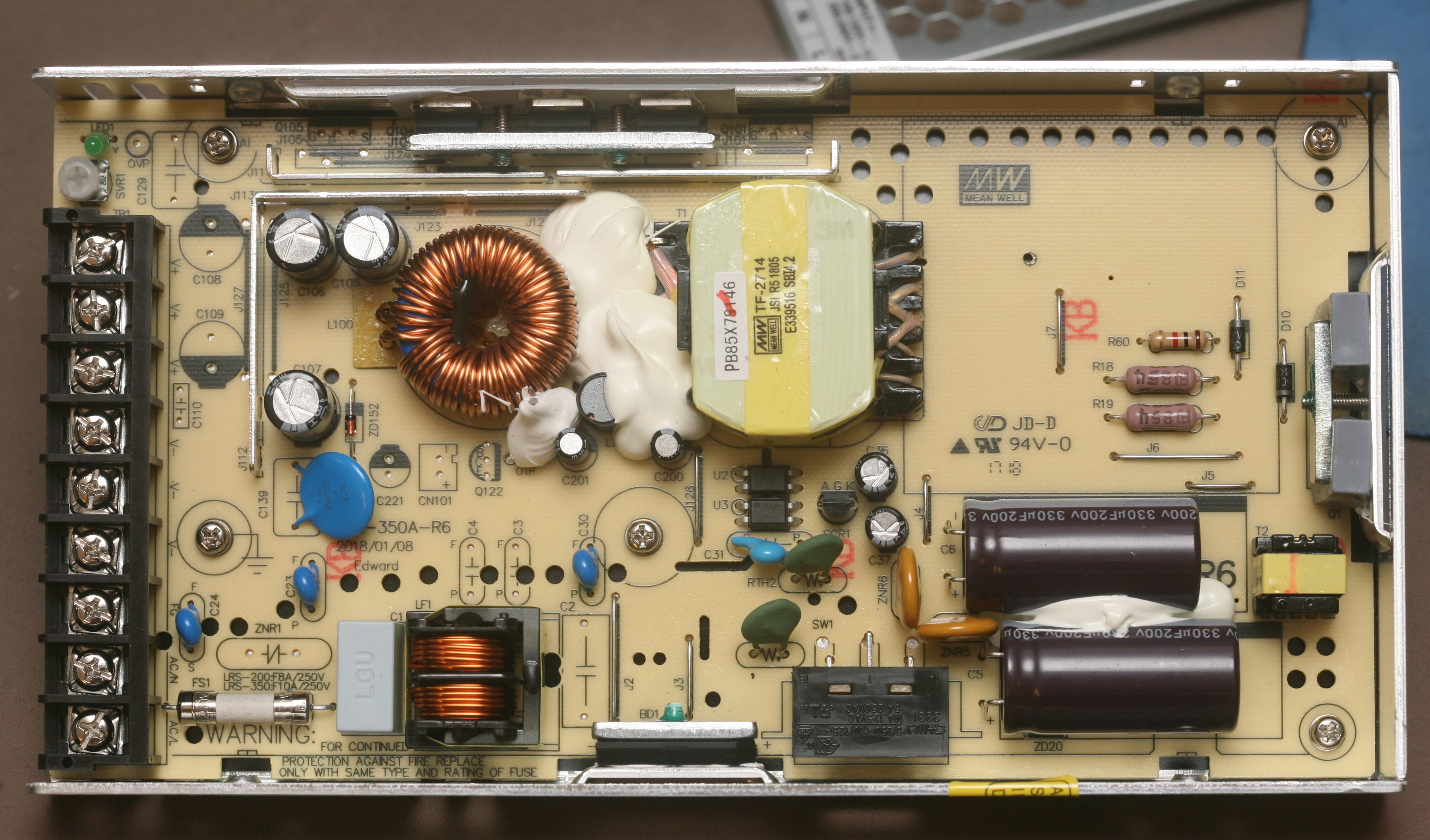
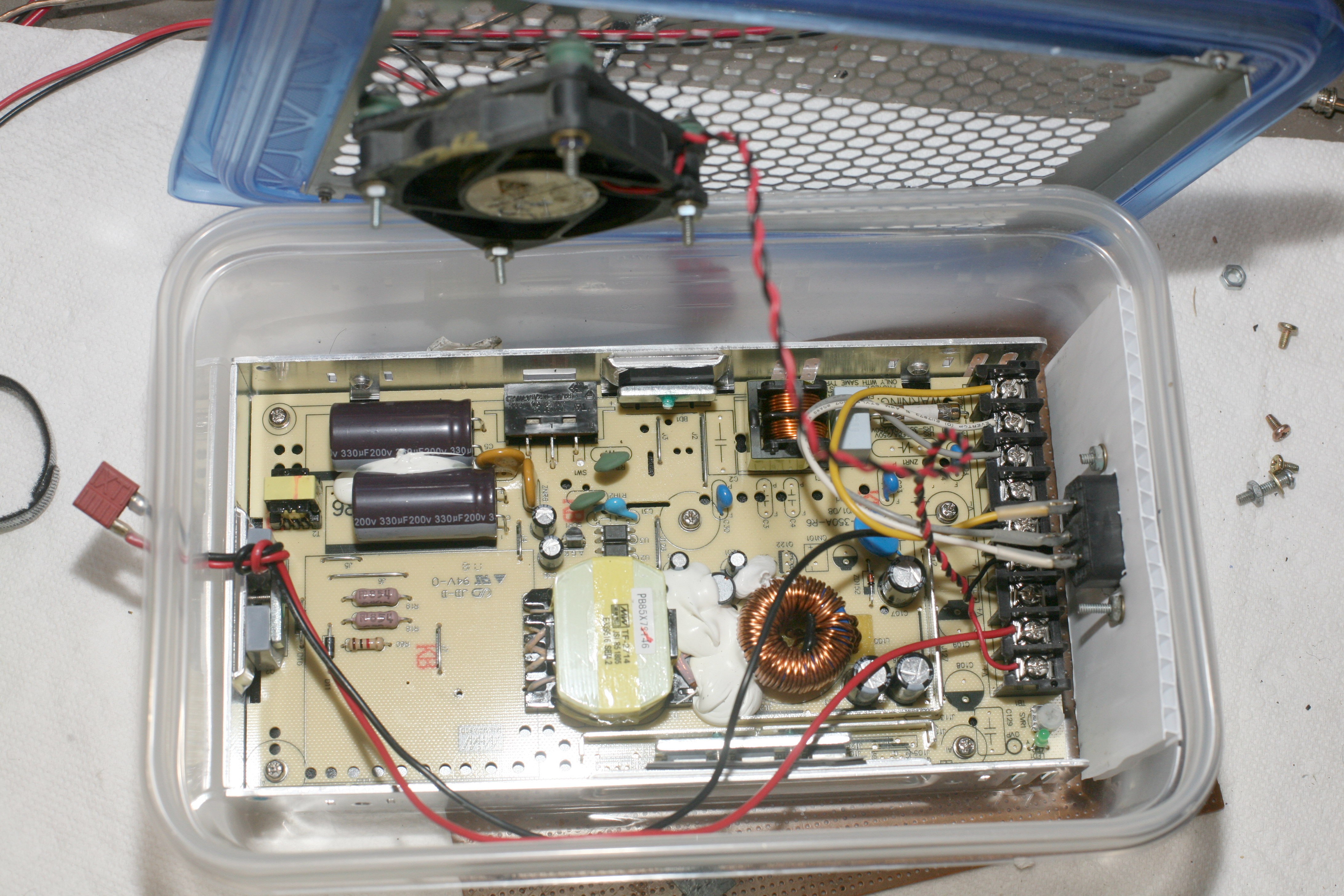
Not described on the internet was that it had no IEC manes connector, no fan, no soft switch. It really was just a bare board with screw mounts.
![]()
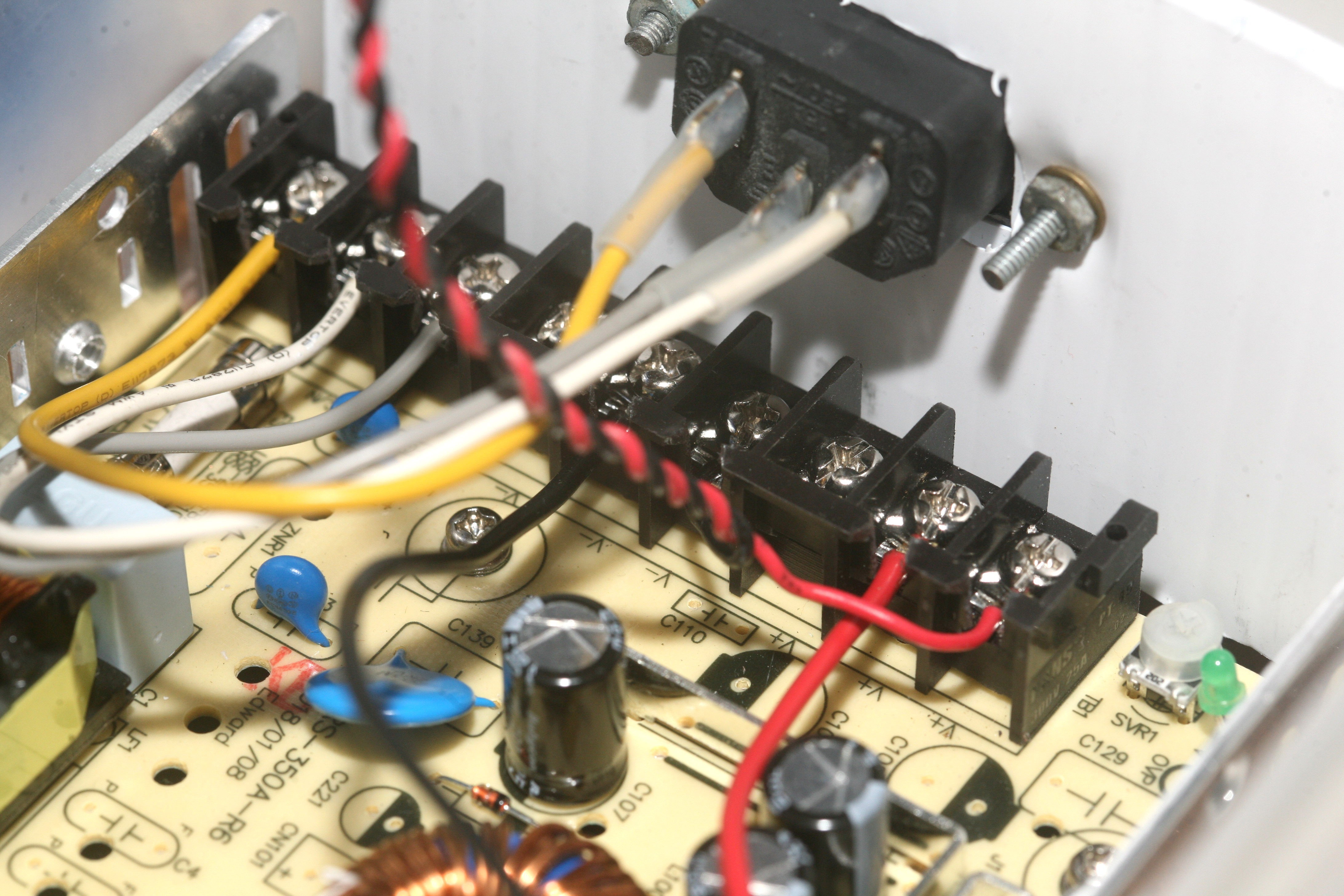
Most of the board was empty, thus giving a very empty space in need of an enclosure. There was a trimpot for adjusting the voltage. The range was 13.5-18V. Fortunately, there was a spare manes connector from the dead 250 watter with ancient style screw holes.
![]()
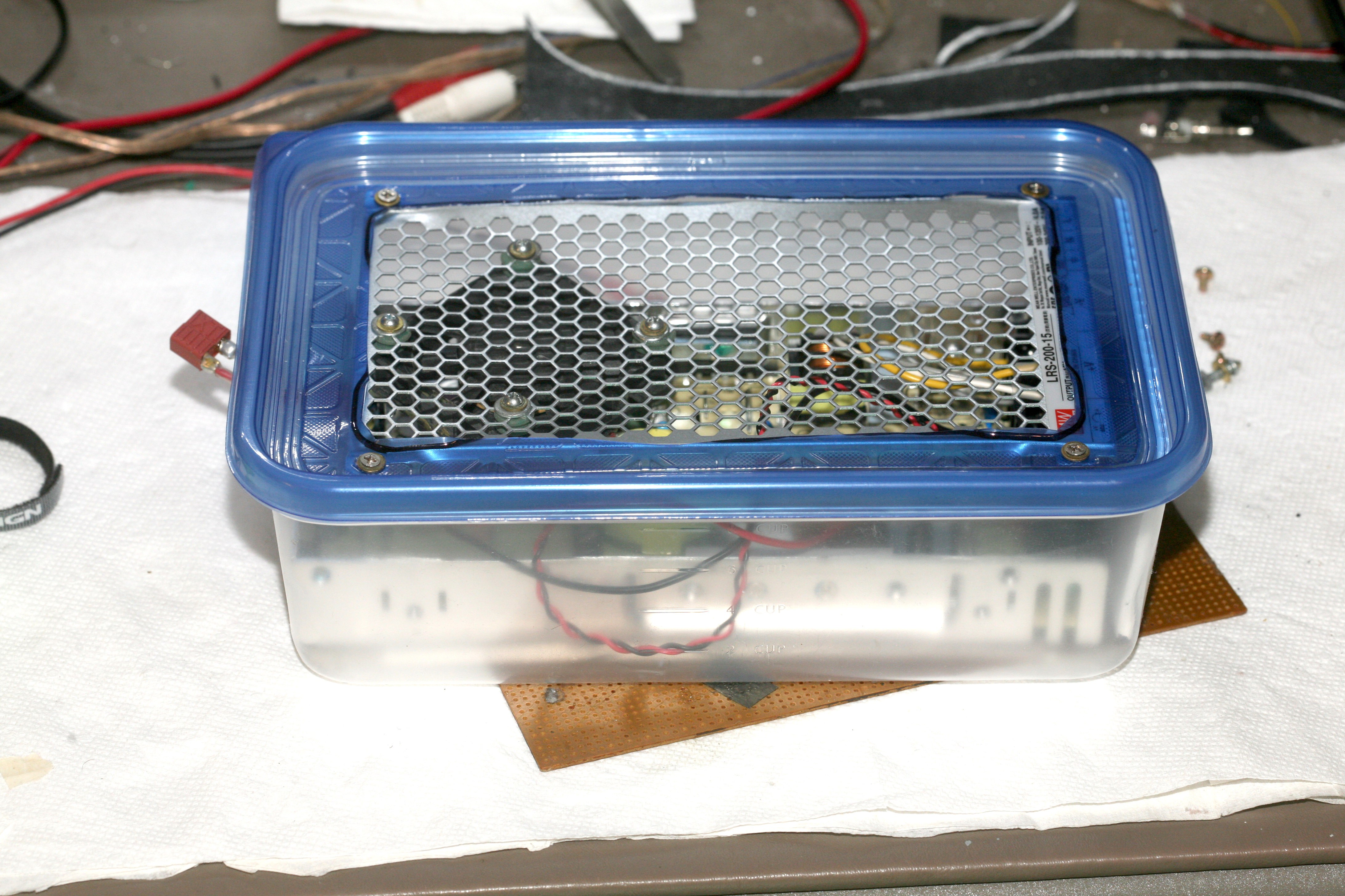
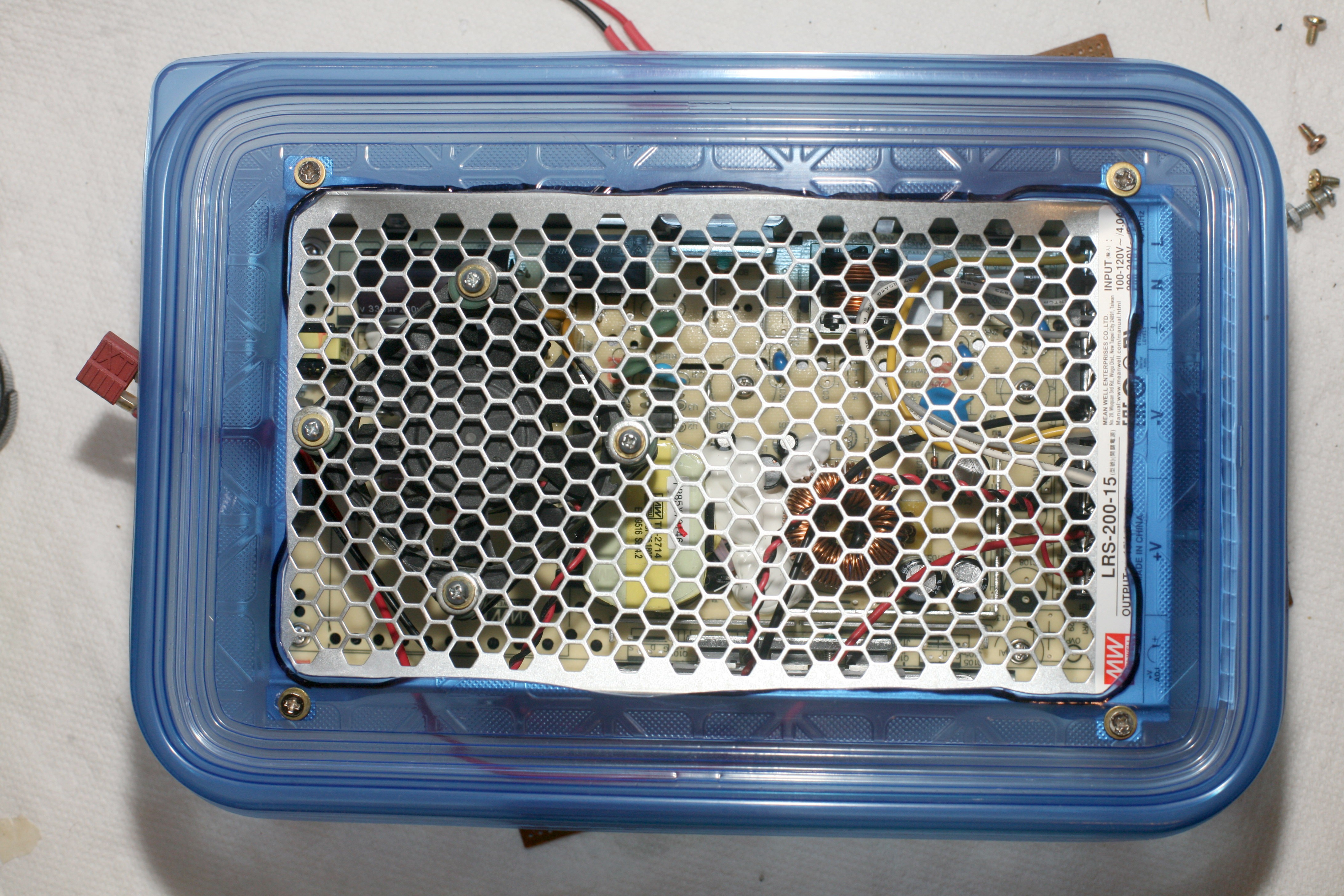
After a day of fabricating, it had been enclosed in tupperware.
![]()
![]()
![]()
The screw mount was modified for easier cable routing. Be sure neutral & GND aren't shorted, live & neutral aren't reversed, the chassis is GND, & your manes are heat shrinked. Test without a load to adjust the pot.
![]()
After 6 months, the LEDs were back. They couldn't get as bright as before, because experimenting with PWM over drove them. You can't drive LEDs with PWM & get the same brightness as a DC voltage.
They were nowhere nearly as bright as a pair of 60W fluorescents, but the fluorescents drove PG&E from $100 to $130/month. Brighter results with LED strips would cost a lot more than edison mounted bulbs of any kind. The power supply is going to be expensive & maxed out.
-
Laptop power supply test
03/21/2018 at 18:40 • 0 commentsDecided it would be easier to take another swing at repairing the vintage AT power supply than trying to hack a modern ATX supply. Quickly spotted a bodge wire melted onto a diode. The diode was shorted. 2 of these diodes rectify the output of the mane transformer, using a center tap. The component that blew was an FR302 diode. Replaced it with a 1N5400 & then a SN30SC4. Both worked without a load, but immediately blew after briefly lighting the LEDs. It pointed to a transformer winding that shorted under load & the short was on one side of the center tap, putting 120V across only 1 diode. That was all for the 20 year old supply. It was back to dropping laptop voltage with PWM.
![]()
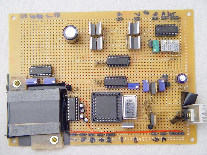
Robot board from 2002
![]()
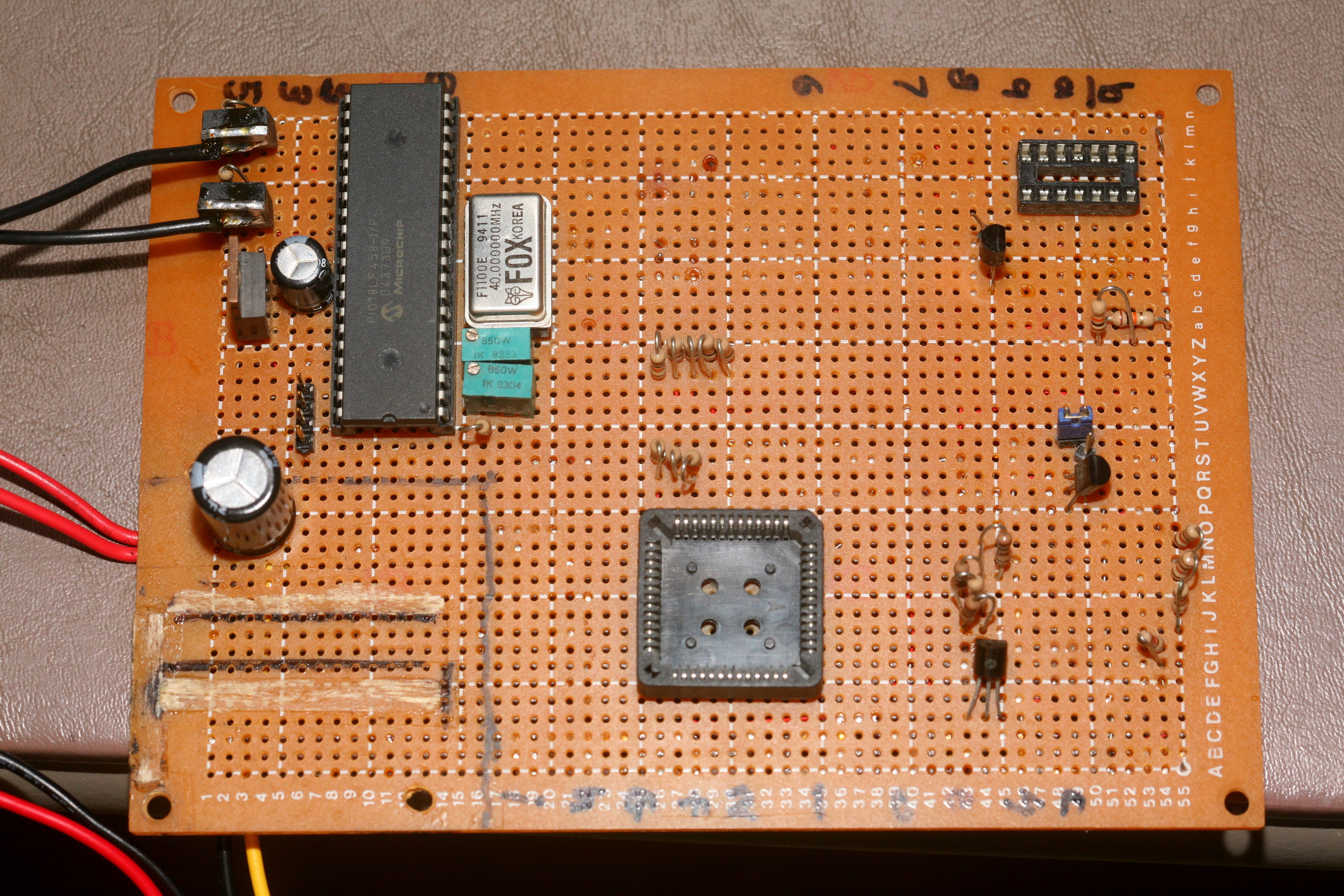
Converted into a PWM board, today
Recycling the very 3rd microprocessor board a lion ever built was a reminder of those days. The board seems to have changed color after 17 years. There was no oscilloscope, no USB, no current limited power, & no temperature controlled soldering iron. Instead of an FTDI chip, there was a MAX232 which plugged into a computer's 9 pin serial port. The attitude was don't build anything that would be cheaper to buy, which led to copying a schematic & hoping it would work. Without an oscilloscope, the 1st microcontroller board was abandoned.
Lions assumed microcontrollers only used the standard baud rates of personal computers when in fact it was an arbitrary number based on the clockspeed. Determining the baud rate was the 1st task in bringing up every later board.
The 68HC11 was the best microcontroller available. It was pathetic, but a friggin computer on a chip. Lions still recycle old microcontrollers, but not as primitive as the 68HC11. The 68HC11 actually had 4 more PWM outputs than the early PICs. It was programmed entirely through the serial port, which made the baud rate critical for getting anywhere with it.
The new dropper used an overkill microcontroller for 1khz PWM, but it's all about retiring these vintage microcontrollers. The LEDs got a lot hotter when pulsed at 1khz than when at DC. What used to run on 9V RMS now got hot at 2.5V RMS & appeared a lot dimmer. The dropper made a clear 1khz sound & the laptop brick got hot.
LED strips may still be too expensive to replace manes voltage floor lamps. Key changes with the giant square would be using interconnects instead of soldering the entire thin PWM is the accepted way of dimming LEDs, but it's obviously very inefficient.g in 1 piece & making the sides equal length. It would be much easier to erect if it used interconnects.
-
Power supply 2.0
03/21/2018 at 07:05 • 0 commentsDeveloping a power supply is harder than it looks. The commercial ones output 12V which drops significantly by the time it reaches the strip. There are multiple, random LED strips with different voltages. Multiple voltage droppers for a single laptop power supply would be the easiest way. After considering how to drop multiple voltages with the cheapest microcontrollers, Mike Harrison introduced a PWM generator based on 2 op amps. 1 op amp generates a triangle wave. The other op amp is a comparator that chops the triangle wave into PWM. It could be far simpler than a microcontroller.
![]()
![]()
LTSpice showed it can work, but it requires higher speed op-amps which are only in surface mount. The trick with LTSpice was arranging the power supplies exactly as shown. A single supply or a -5V supply didn't work. It would actually take more parts than a single microcontroller.
-
Death of the LED square
03/20/2018 at 00:43 • 0 commentsIt worked for several weeks, then suddenly went dark & the power supply let out the magic smoke. The power supply was dropped. It somehow cracked a fan blade, causing it to stop. It must have over heated & fried a component. 12V was shorted to ground. All the caps were intact. It was probably a delaminated transformer winding. There was only 1 more supply, a 2005 era 500W deal. All the others from before 2001 were recycled to conserve space. It used a PS223 protector but had no obvious voltage regulator on the low voltage side. That was the end of computer power supplies.
The next step would be making another PWM circuit for another 90W laptop power supply. The total number of new PWM circuits would be 2, since using a transistor as a resistor is super inefficient.
Ultimate lighting
There has long been a dream of replacing all the floor mounted lighting with anything more practical.
 lion mclionhead