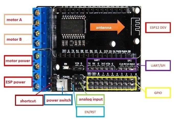
ESP motorshield
There's not so much information on the Internet about this board. First of all this shield for ESP-12E Dev Kit and NodeMcu boards and not for all, because width between pins is 25mm and that's not enough for some boards like LoLin. In my project I used NodeMcu Amica.
Schematics of shield
This shield board is driven by the special excent large power full-bridge chip L293DD from the famous Stmicroelectronics company, which can directly drive 2-channels DC motors or one-channel stepper motor. The driven current can be arrived at 1.2A.
Motor power: can be up to 36V.
ESP power: can be up to 9V. Because it goes straight to the esp without any voltage regulators.
Also these pins have common ground, you can connect voltage supply to one pin and use shortcut for other(if voltage less than 9V).
Board uses 4 pins to control motors. PWMA, PWMB- speed of motors. DA, DB-direction of motors(0-straight;1-reverse).
Here pinout for NodeMcu Amica.
- PWMA-GPIO5.
- PWMB-GPIO4.
- DA-GPIO0.
- DB-GPIO2.
Circuit

That's how I connected all this stuff. For power supply I use 2 Samsung INR18650-30Q connected in series. About motors, I connect 2 motors in parallel to each motor outputs- PWMA(Left side), PWMB(Right side).Make sure that motors will rotate in one direction when you connect it.
Blynk application
In Blynk application we need only joystick.


Joystick settings
Set joystick to merge mode for work with Virtual pins. Values for both axis from (-1) to 1.
ESP code
Esp code is default Blynk project with handling data from joystick at Virtual pin- 1.
#define BLYNK_PRINT Serial
#include <esp8266wifi.h>
#include <blynksimpleesp8266.h>

// You should get Auth Token in the Blynk App.
// Go to the Project Settings (nut icon).
char auth[] = "YourAuthToken";

// Your WiFi credentials.
// Set password to "" for open networks.
char ssid[] = "YourNetworkName";
char pass[] = "YourPassword";

int PWMA=5;//Right side
int PWMB=4;//Left side
int DA=0;//Right reverse
int DB=2;//Left reverse

void setup(){
 // Debug console
 Serial.begin(9600);
 Blynk.begin(auth, ssid, pass);
 pinMode(PWMA, OUTPUT);
 pinMode(PWMB, OUTPUT);
 pinMode(DA, OUTPUT);
 pinMode(DB, OUTPUT);
}

void loop(){
Blynk.run();

}

// Handling Joystick data
BLYNK_WRITE(V1){
int x = param[0].asInt();
int y = param[1].asInt();
if(x==-1 && y==-1){             //Backward and Left
     digitalWrite(PWMA, LOW);
     digitalWrite(DA, LOW);

     digitalWrite(PWMB, HIGH);
     digitalWrite(DB, HIGH);
}else if(x==-1 && y==0){        //Left Turn
     digitalWrite(PWMA, 450);
     digitalWrite(DA, HIGH);

     digitalWrite(PWMB, 450);
     digitalWrite(DB, LOW);
}else if(x==-1 && y==1){        //Forward and Left
     digitalWrite(PWMA, LOW);
     digitalWrite(DA, LOW);

     digitalWrite(PWMB, HIGH);
     digitalWrite(DB, LOW);
}else if(x==0 && y==-1){        //Backward
     digitalWrite(PWMA, HIGH);
     digitalWrite(DA, HIGH);

     digitalWrite(PWMB, HIGH);
     digitalWrite(DB, HIGH);
}else if(x==0 && y==0){        //Stay
     digitalWrite(PWMA, LOW);
     digitalWrite(DA, LOW);

     digitalWrite(PWMB, LOW);
     digitalWrite(DB, LOW);
}else if(x==0 && y==1){        //Forward
     digitalWrite(PWMA, HIGH);
     digitalWrite(DA, LOW);

     digitalWrite(PWMB, HIGH);
     digitalWrite(DB, LOW);
}else if(x==1 && y==-1){        //Backward and Right
     digitalWrite(PWMA, HIGH);
     digitalWrite(DA, HIGH);

     digitalWrite(PWMB, LOW);
     digitalWrite(DB, LOW);
}else if(x==1 && y==0){        //Right turn
     digitalWrite(PWMA, 450);
     digitalWrite(DA, LOW);

     digitalWrite(PWMB, 450);
     digitalWrite(DB, HIGH);
}else if(x==1 && y==1){        //Forward and Right
     digitalWrite(PWMA, HIGH);
     digitalWrite(DA, LOW);

     digitalWrite(PWMB, LOW);
     digitalWrite(DB, LOW);
 }
}
Nothing complicated, data handling is done by if-else if...
Test
All is done! Here video with tests.

 PuriBottle
 TasosY2K
 ElectronicABC
 Max-Felix Müller