 piotrb5e3
The choice of a microcontroller
I searched my drawers for unused MCUs and came up with the following:
| Device | Current consumption (in power-saving mode) | Minimum voltage | Package |
|---|---|---|---|
| ATmega328P | 1μA | 1.8V | DIP28 |
| ATtiny13A | 4μA | 1.8V | SOIC8 |
| AT89C2051 | 1mA(1) | 2.7V | DIP20 |
| STM32F070F6P6 | 2μA | 2.4V | TSSOP20 |
| STM32F051K8T6 | 0.8μA | 2V | LQFP32 |
| STM32F103C8 | 2.6μA | 2V | LQFP48 |
(1) - it has a power-down mode, but the only way to exit it is a hardware reset
We can discard ATmega328P and AT89C2051 because of large packages. Then STM32F051K8T6 and STM32F103C8 because of hard to solder packages. Looking at a generic cr2032 datasheet we see that the 1.8V minimum supply voltage of ATtiny13A isn't much of an advantage. But the STM32F070F6P6 is a much more complex device. Let's check if halving power consumption is worth it.
Going back to the datasheet we read that a typical cr2032 has the capacity of around 200mAh. At 2μA it makes for 200mAh/0.002mA = 100000h ≈ 4166 days ≈ 11 years. At 4μA it's ≈ 5.5 years. Scaling it back to our 1 year battery life target we get 9% and 18% of power consumption going to the powered-down MCU respectively. A 9% total efficiency increase is not insignificant.
Nevertheless I decided to go with the ATtiny13A, as it's a simpler design, and I'm already familiar with it.
Let there be (invisible) light!
I quickly wrote a short 38kHz bit banger for the ATtiny13A using the NEC transmission protocol (see the source code), and assembled a simple circuit (schematic PDF).
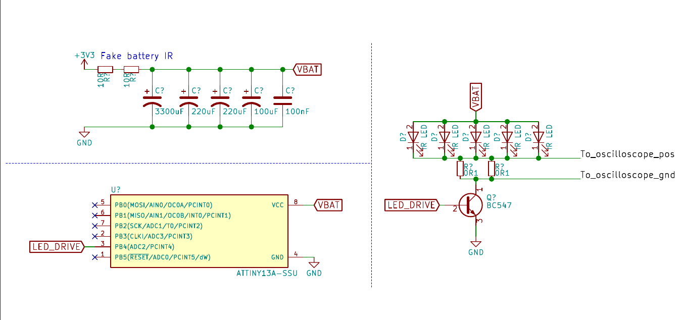
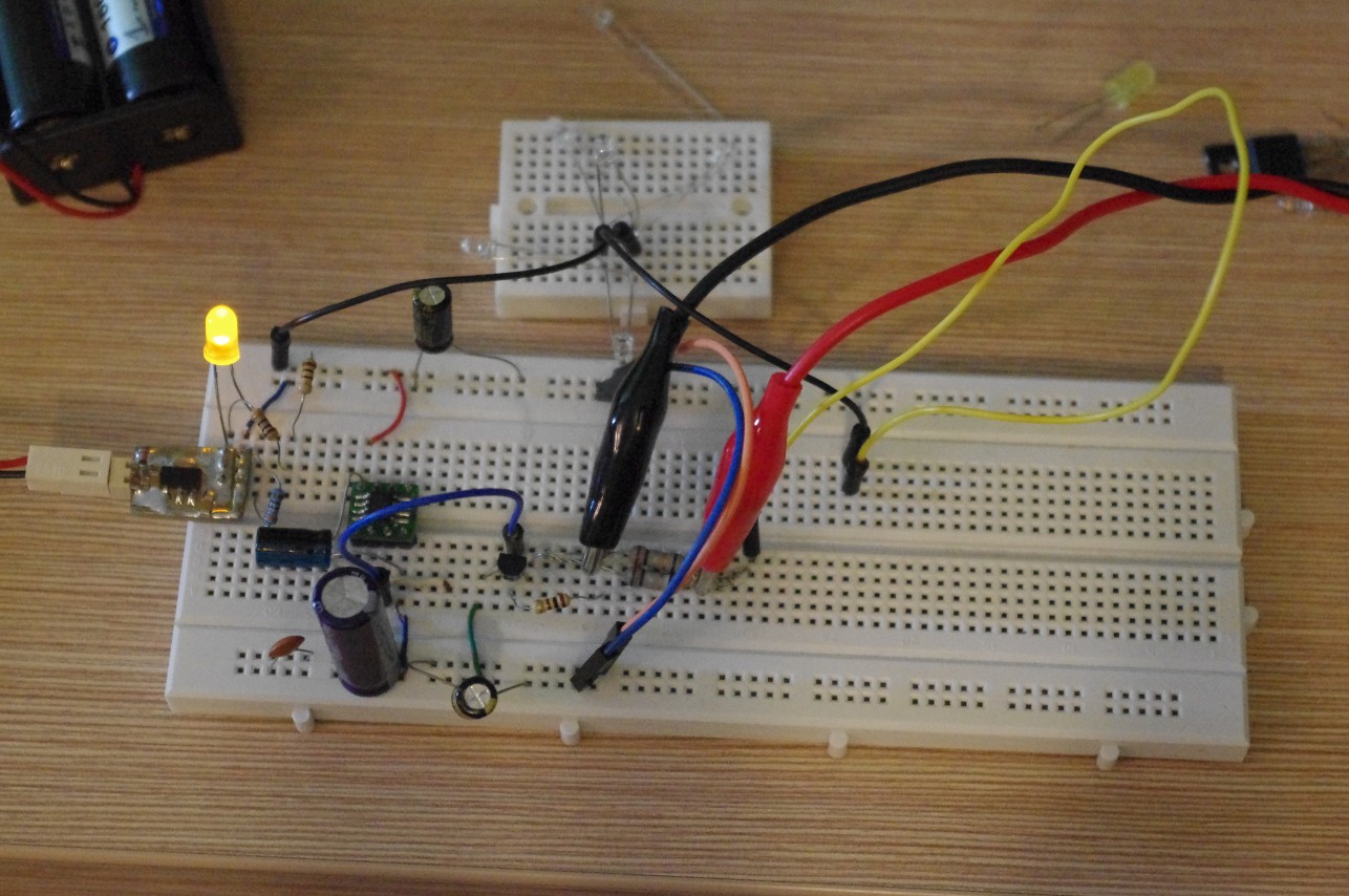
This is the final iteration. At first I tried driving the IR LED directly from a microcontroller pin, but the range was poor due to a 40mA current limit. A MOSFET would be ideal, but none of those I stock has VGS (th) < 3V.
I used 2 10Ω resistors in series with a 3.3V regulated power supply to mimick the internal resistance of a cr2032 cell. Multiple large electrolytic capacitors are used to provide a low ESR power rail for high current LED pulses.
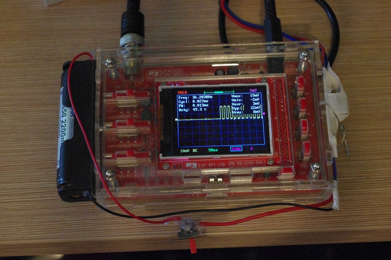
I measured the peak current with an oscilloscope connected across two paralell 0.1Ω resistors. It peaked at 0.02V over 0.05Ω which gives us 0.02/0.05 = 0.4A = 400mA.
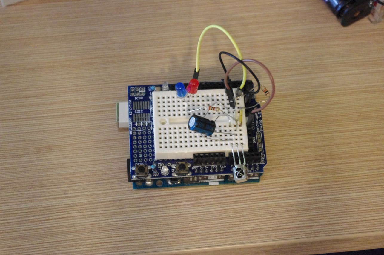
I built a simple receiver and was able to read the transmitted data clearly across the hallway in my home - around 13m across. Field test will be required to check actual broadcast range. The receiver is a simple circuit with 2 status LEDs - the blue one blinks when the correct sequence was received, and the red one when an incorrect sequence was received.
The envelope
Let's dial down the current and consider a 100mA peak drive. A 32-bit transmission with the NEC protocol consists of a 342-pulse header, 32 bit markers of 21 pulses each, and a 21-pulse ending sequence. Each pulse is 13μs long. This gives us 342 + 32*21 + 21 = 1035 pulses per transmission, for a total of 13.455ms of high current draw. Additionally, the microcontroller will be active for at least 70ms at a current draw of around 2mA. This adds up to 13.455ms*100mA + 70ms*2mA ≈ 0.000413mAh.
After substracting the power needed for the idling MCU we are left with around 160mAh of battery capacity. This will allow us to transmit around 387409 times. In a year, that makes for 387409/(365*24) = 44 transmissions per hour. It's 30% less than my intended target of once-per-minute, but at least we are in the right ballpark.
One final note: electrolytic capacitors have a considerably high (tens of μA) leakage current. Because of that they should be avoided in low power applications. We'll have to do with just ceramics.
Discussions
Become a Hackaday.io Member
Create an account to leave a comment. Already have an account? Log In.