 suedbunker
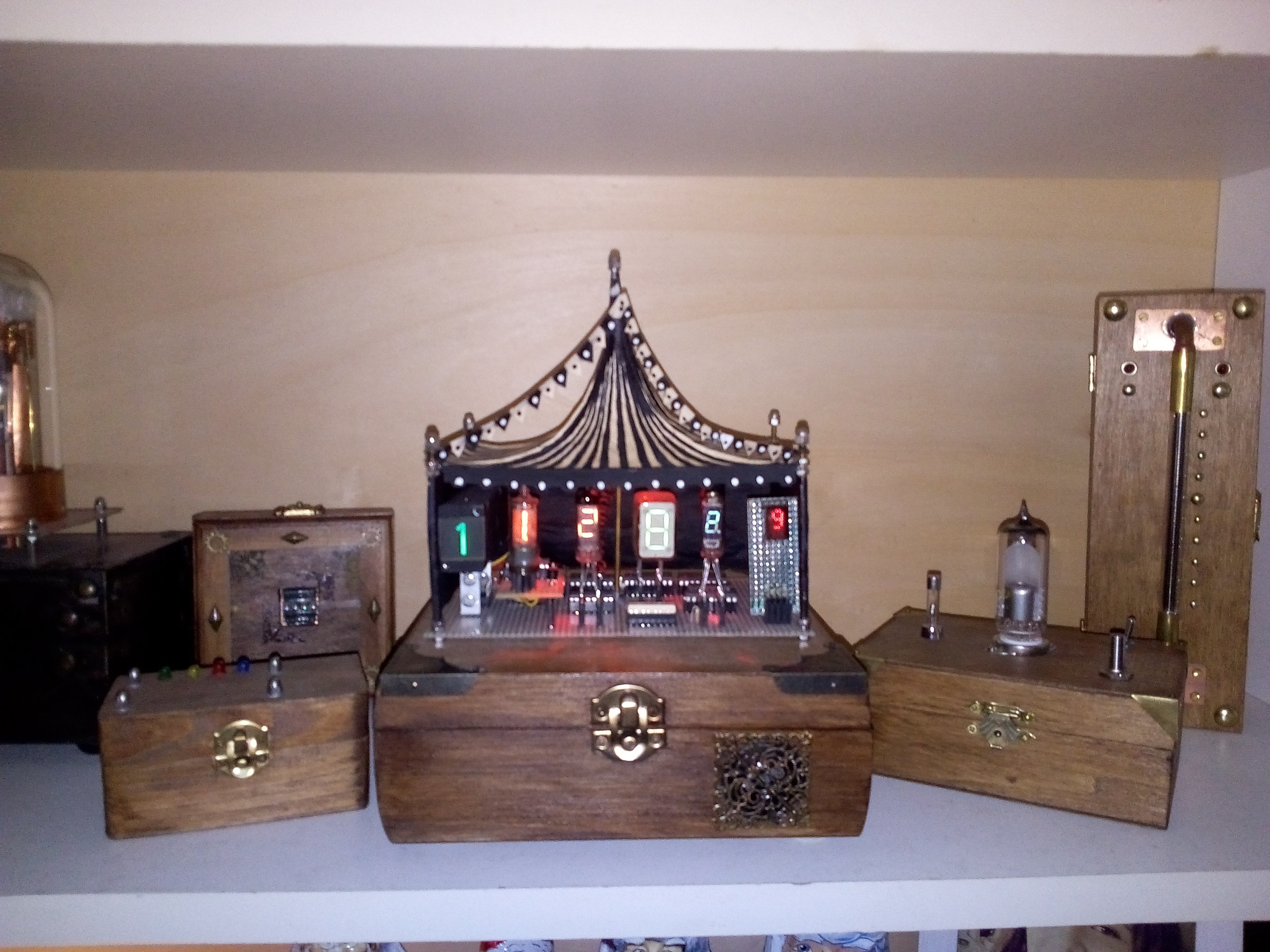
Foreword:
This is not a complete description with all the circuits, .stl files and predigest “how to” chi chi. This is only a collection of all information and links you will need to build such a clock. It is more a learning manuscript or a badly written manual. I have tried to keep it short but informative. Read the datasheets in the links a have collected, make a lot of handwritten notes! Write a date on it! Use a pencil and any peace of paper! Write down what you plan and what you did! I am sure that the PCB and code etc. is not perfect. Build your own punk clock! Tuwat and h4ck the pl4net!
Segments:
I decide to build a punk clock with all the beauties of electronic numbers. So there are different methods from using a slide with a matt screen over glowing plasma and semi conductors.
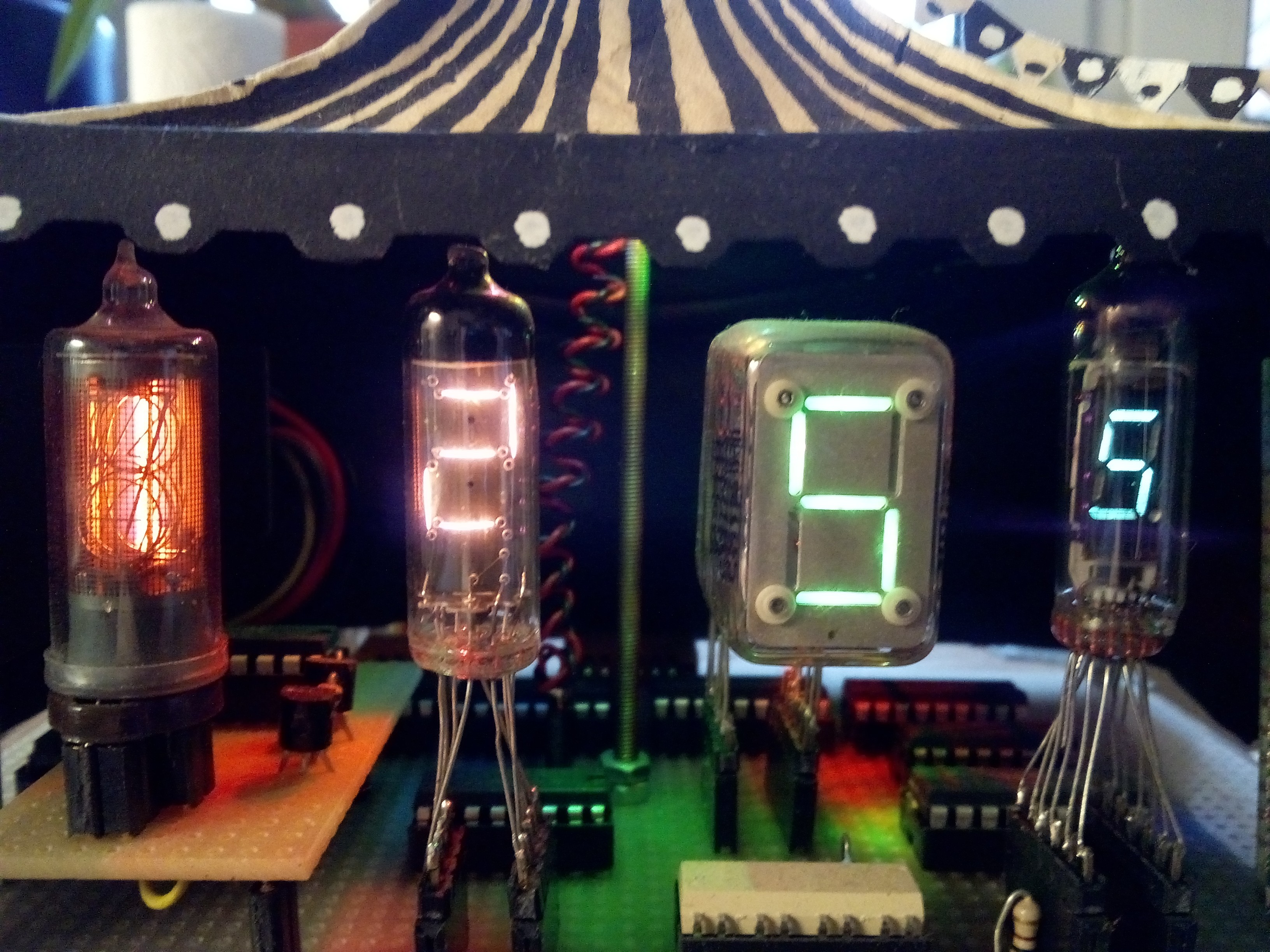
Following the different segments I have found:
An old projector from an organ. This is a real little projector with 12 little bulbs and 12 little slides with the numbers 0-9, a dot and some letters. The illuminated number is visible on a matt screen. I replace the classic bulbs with RGB rainbow LEDs, just for the effect. I think it is from the 1950th or 60th. And maybe the oldest segment. Thanks to [Bendixxx] for this gift!
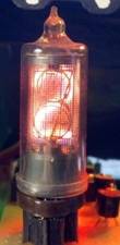
A Nixie tube. Some years ago I have found an old counter from HP with a Nixie tube array. Six of them are in my first Nixie clock and the left over one is now in my circus clock. It is a B-5750 from Burroughs Corporation Datasheet:
http://www.tube-tester.com/sites/nixie/data/b-5750.htm
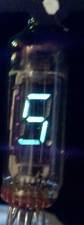
Then a Russian Numitron tube IV-8 from e-Bay as Old New Stock Part. Quite simple to control. The segments are just filaments with about 30mA. You can use this instead of an LED seven segment. Datasheet: http://www.tube-tester.com/sites/nixie/data/IV-9/iv-9.htm
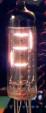
This is my favourite unless it is a little complicated to run this jewel. An ITS1A Thyratron tube. Three different voltages and an unhandy protocol to generate a number plus the weird method to bring this little phosphorus filled segments with secondary electrons to glow. Datasheet: http://www.industrialalchemy.org/articleview.php?item=1073
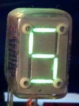
A vacuum fluorescence seven segment tube is the next one. I choose an IV-8. Datasheet:
http://www.tubetester.com/sites/nixie/dat_arch.html
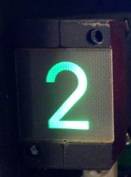
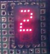
The last one in the clock is a LED dot seven segment unit with BCD encoder HP 5082-7300. I think this is the youngest in the team. Datasheet: http://www.s100computers.com/My%20System%20Pages/ZFDC%20Board/HP5082-73xx.pdf
Power Supply:
This was the most intensive work, also to think about this and to combine some circuits, also the testing and controlling via oscilloscope. All the tubes need a lot of different voltages. The following voltages are used to drive the tubes:
- +5V for the common electronics like LEDs, IDS1416P and the Arduino Nano
- +45V for the ITS1A and for the vacuum fluorescence tube (Booster 1)
- +90V for the ITS1A (Booster 1)
- +150V for the Nixie tube (Booster 2)
- -270V for the ITS1A (Booster 1)
The main input is 12V over a switching power supply (wall wart). The 5V will be generated with a 7805 and some capacitors.
To generate the high voltage a simple boost converter basis was used like on the page from Ronald Dekker and Frans Schoofs. (Thanks a lot for this great page) http://www.dos4ever.com/flyback/flyback.html
I changed the R4, R5 and R6 for generating different voltages. (Fig. 3) In a normal mode this circuit can produce about 300V without any voltage multiplier and changed resistors. I used this circuit a lot and it is really a good alternative to the fancy boost chip you can find on the market. The NE555 is cult.
Two of these boost converters generating the needed voltages in the circus clock. To multiply the voltage especially for the ITS1A voltage doubler were used. https://en.wikipedia.org/wiki/Voltage_multiplier
I used a circuit like in the nixiekit.eu webpage for the ITS1A clock:
http://www.nixiekits.eu/Downloads/SCHEMATIC1.pdf in the lower left corner. Also a great project!
Read this circuit carefully to understand the controlling of the ITS1A. It is a wonderful project.
In the following picture the voltage multiplier is shown witch was used in the circus clock. The main boost converter produced 45 V as primary voltage. The first voltage multiplier will double the voltage to 90 V and a 6 fold negative voltage multiplier will produce -270 V. the PWM for the boost converter is linked to the RFD MOSFET in the middle on the left side. I used the common 1N4007 diodes. 100n was used for the capacities.
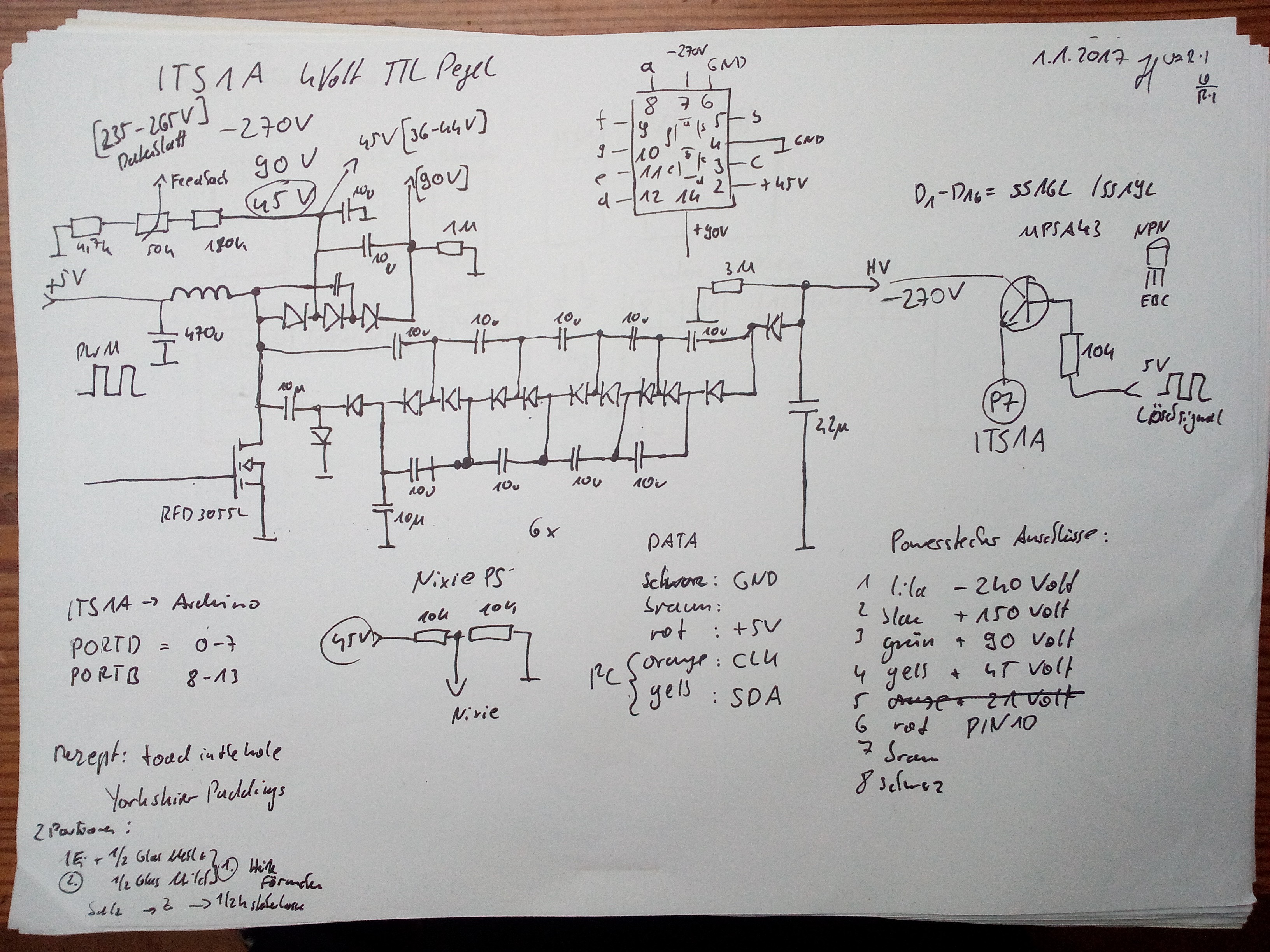
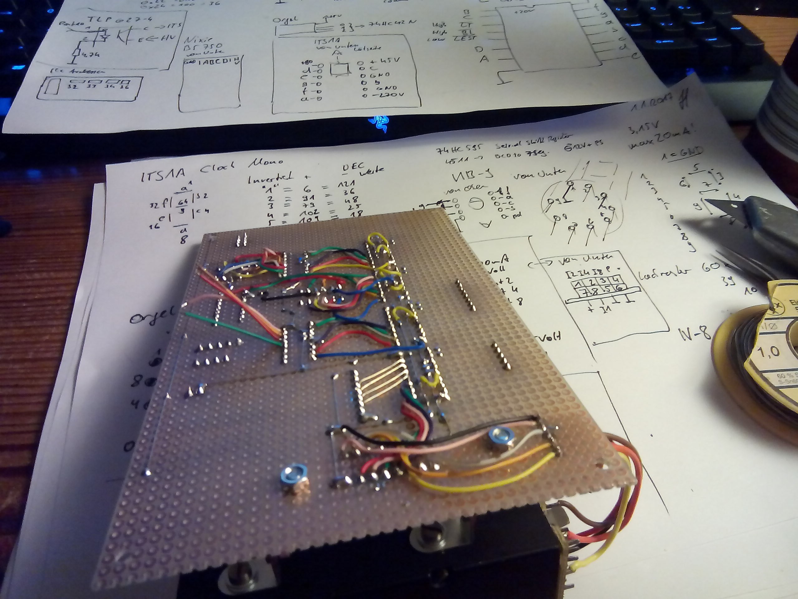
Sketch from my power supply for the ITS1A. In the middle above a connection sketch from the ITS1A is drawn. Down left a recipe for toad in the hole. J
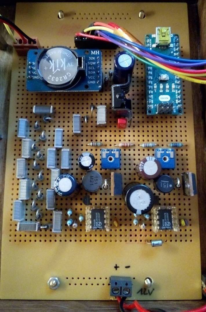
RTC, Arduino Nano and Power supplies. Left on the top of the PCB the real time clock was placed. Then to the right the 7805 for the logic power and the Arduino Nano on the right side. Below from of the left side the voltage multiplier for the -270 V (A lot of capacitors and diodes). In the right lower corner the two boost converters were placed. The right one produce power for the Nixie the left booster produce power for the vacuum fluorescence and ITS1A tube.
Control over I2C and BCD:
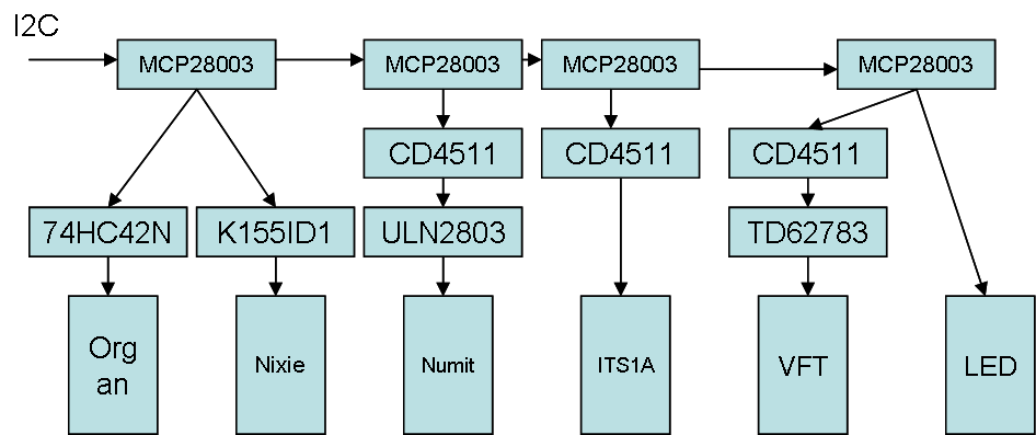
Four MCP23008 control the single segments. The addresses 32, 33, 34 and 36 where used. The ITS1A use a single MCP for controlling each single segment in the tube. The VFT and HP LED will be controlled with the upper and lower four bit oft a MCP like the Organ and Nixie unit does. The Numitron tube uses a single MCP with just the lower four bit.
To control the seven segment tubes I decide to use I2C and four port expander MCP23008 followed by BCD to 7 segment drivers like the CD 4511. Datasheet:
http://www.ti.com/lit/ds/symlink/cd4511b.pdf
The organ projector uses a 74HC42N as BCD to ten decoder. Remember every single number is a small slide with lens and LED. It is a discrete picture and needs only one pin for display a number. Datasheet:
http://pdf.datasheetcatalog.com/datasheet/NXP_Semiconductors/74HC_HCT42_CNV.pdf
The HP LED dot display has an intern BCD converter to show different numbers.
To drive a vacuum fluorescence tube you have to use 20-50 V. This was solved by using a high side driver like the TD62783. The signal from the BCD to seven segment counter would be switch the high side driver. The single segments of the vacuum fluorescence tube will then be powered by the high side driver. Datasheet:
http://pdf1.alldatasheet.com/datasheet-pdf/view/32296/TOSHIBA/TD62783.html
For the Numitron tube a ULN2803 low side driver was used. There is no polarity so I used what I have found. Datasheet:
http://www.alldatasheet.com/datasheet-pdf/pdf/12687/ONSEMI/ULN2803.html
The Nixie tube needs a special high voltage driver to handle 150V. I the circus clock the Russian K155ID1 IC was used: http://tubehobby.com/datasheets/k155id1.pdf . This chip can handle the high voltage and combined this ability with a BCD encoder for the numbers 0 to 9.
RTC:
As RTC I used a DS3232 module from China. There are libaries for the Arduino code. See code at the end of this manuscript.
Sound:
Yeah! It is circus time! Also this clock needs a sound module for playing a silly circus sound at every full hour. For this function a sound module with an ISD1416P (Datasheet: http://www.datasheetspdf.com/pdf/261234/ETC/ISD1416P/1) Now to the sound: I found this gem in the internet on YouTube: (https://www.youtube.com/watch?v=zjedLeVGcfE) I recorded second 11 to 27 over the pc speaker and the microphone on the sound module. The result was a really crappy sound which is perfect for this application in such a wooden box. The sound module is activated by a high port over pin 5 from the Arduino. At every moment when a real serious topic was discussed in our kitchen and the circus clock plays the sound at the full hour. Epic!
Speaker cover for the 8 ohm 1 W speaker of the IDS1416P module at the front of the circus clock.
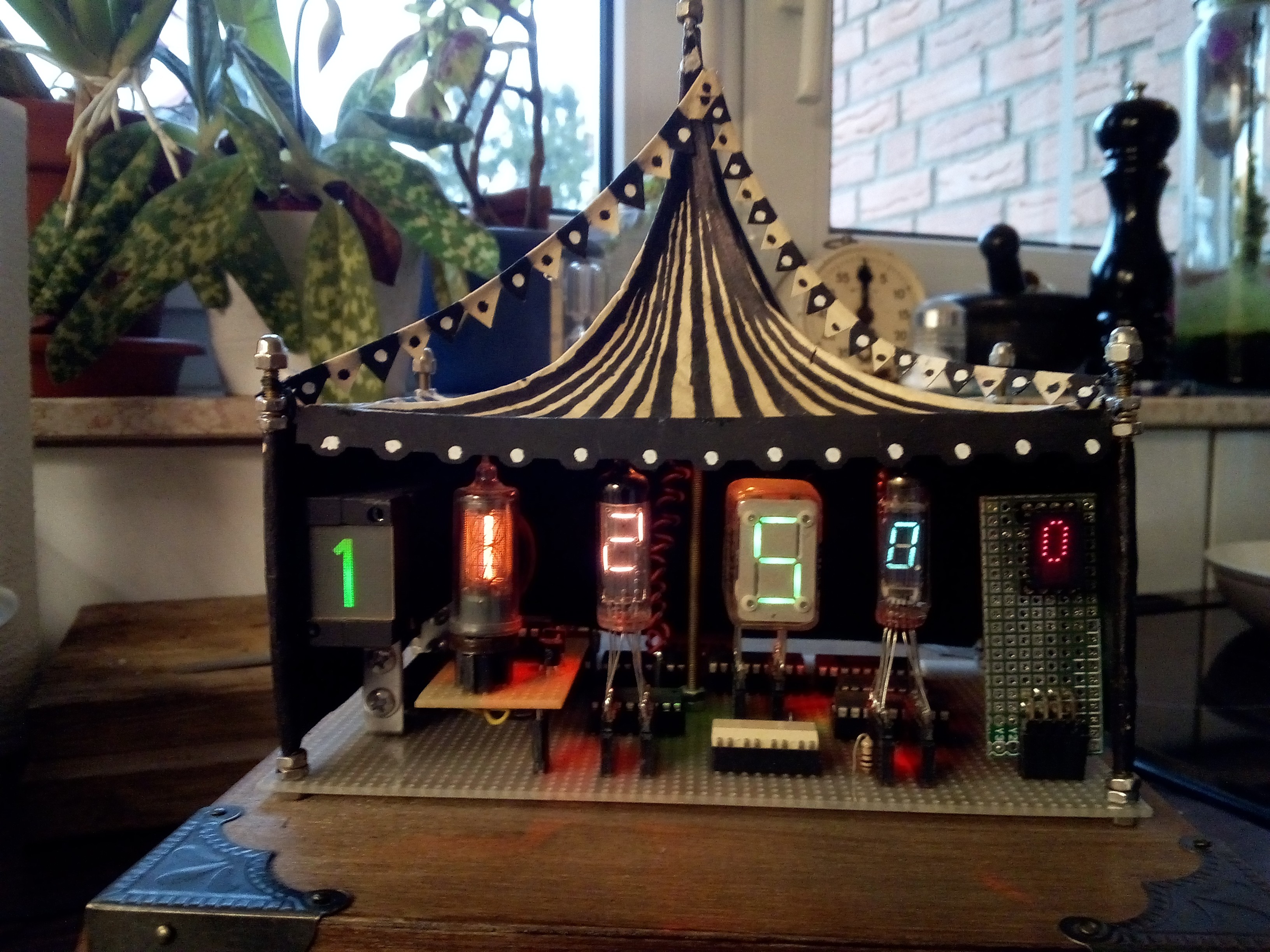
Tent:
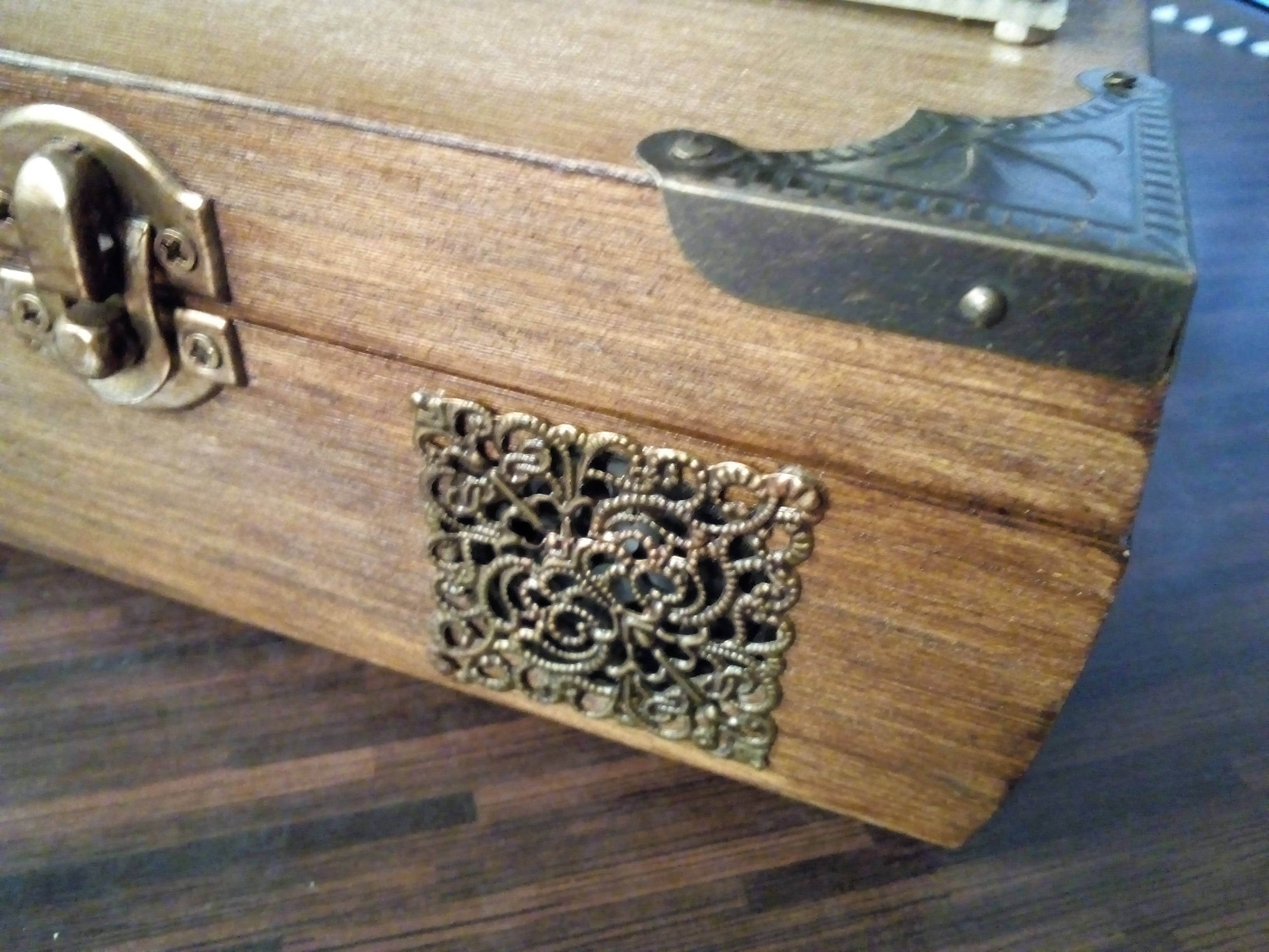
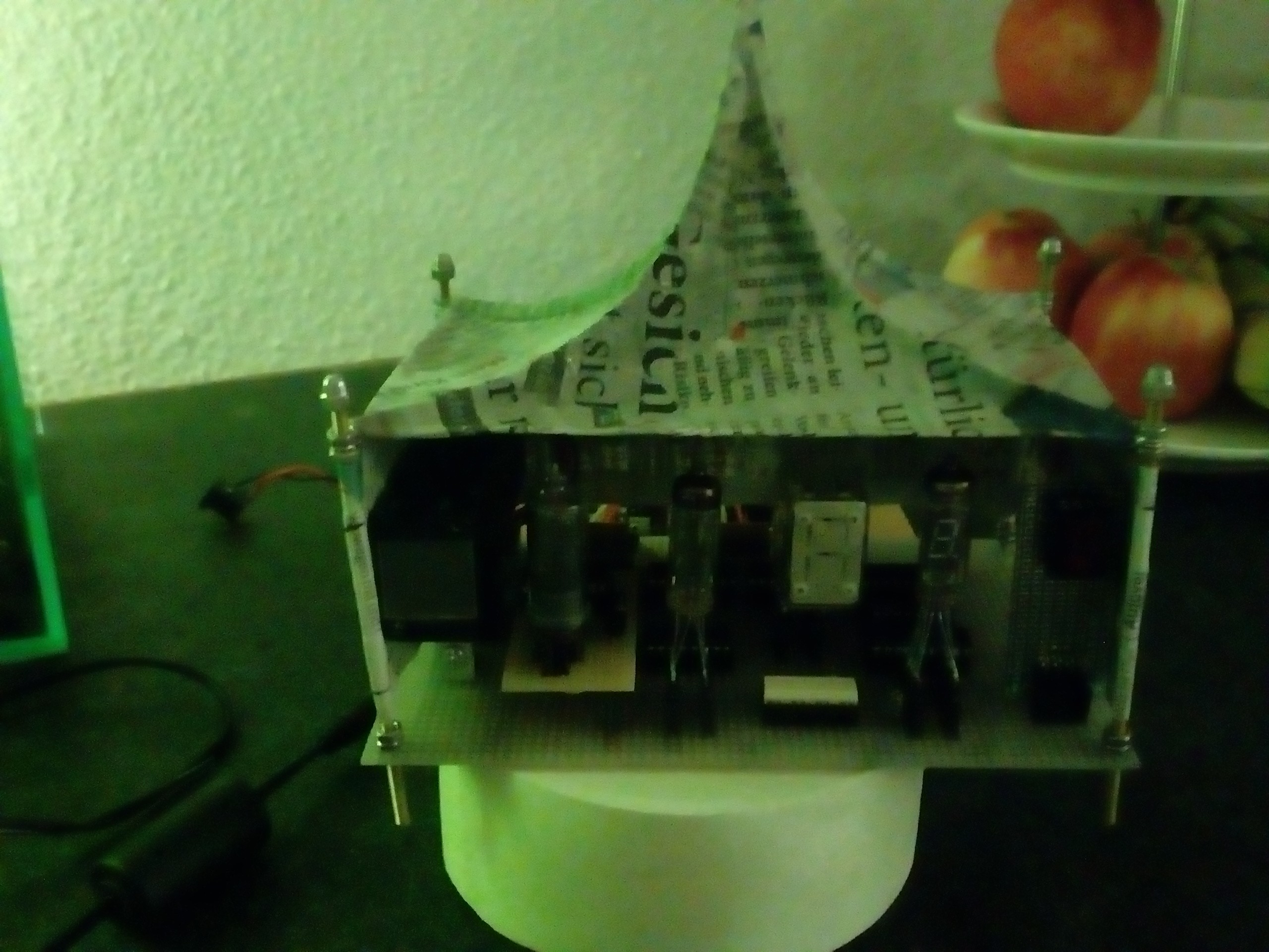
Tim Burton is great; I love this slightly bleak, morbid style. Fantastic! But my lovely wife Madame Fu is much greater than Tim Burton (Sorry Mr. Burton). My wife is a true artist with every plastic things and fabric. So we decide to give the clock a home, a tent. A tent in a kind of Tim Burton is making a movie about an old circus and there habitants. Madame Fu uses newspaper and wallpaper paste for the walls of the tent (papier mâché). I have soldered a simple frame out of 0.3 mm silver coated copper wire. As uprights I used 3mm brass thread rods with domed cap nuts. The uprights are fixed with nuts directly on the PCB.
Date and Time:
In the nominal mode the time is shown on the segments. From second 40 to 47 the date is shown. Sometimes it is scary how often the date was observed over a day.
Pictures and Impressions:
 More Circus!
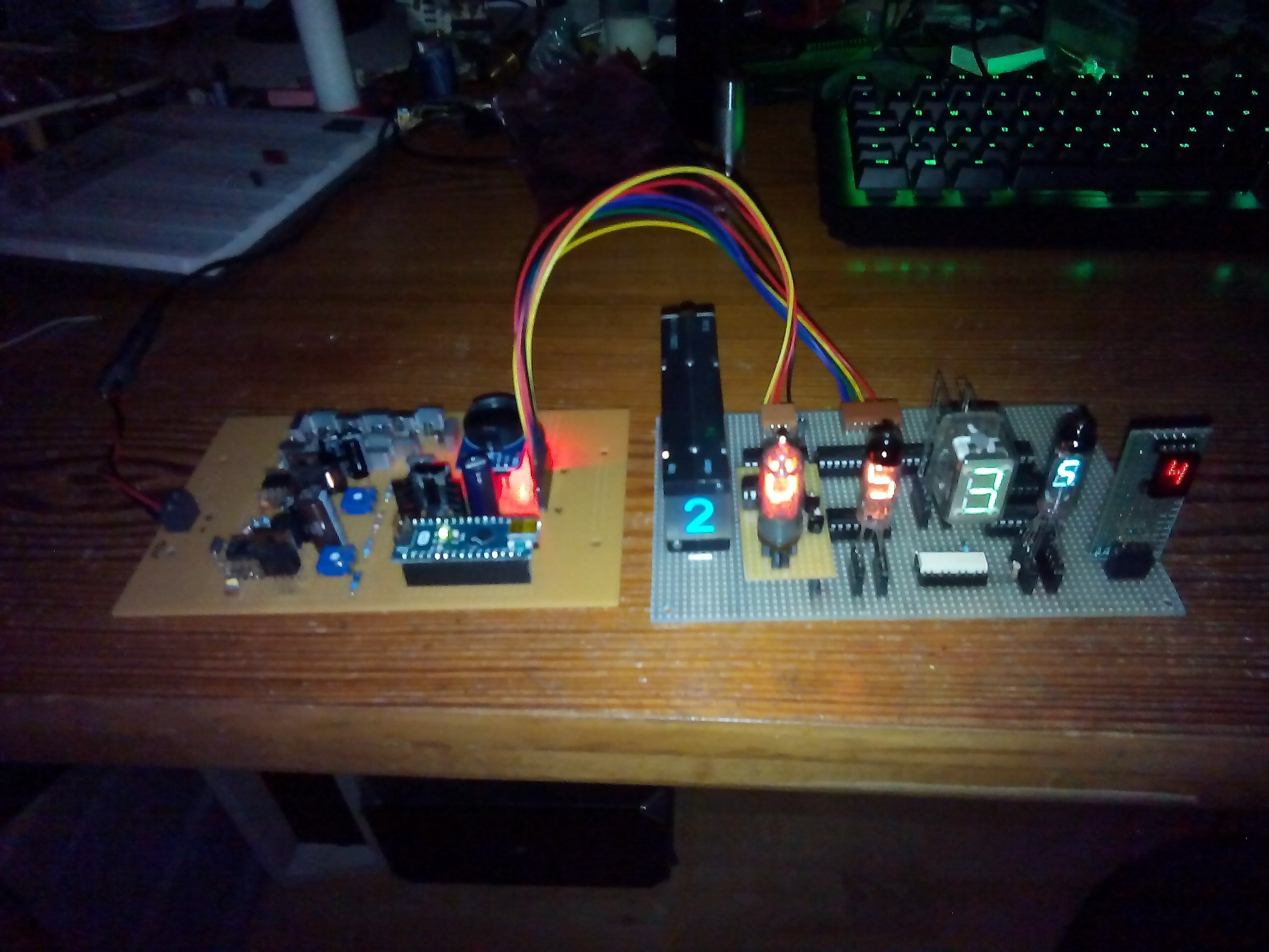
Igor! It is alive! Bring the video camera and don´t forget the Aspirin for my head!
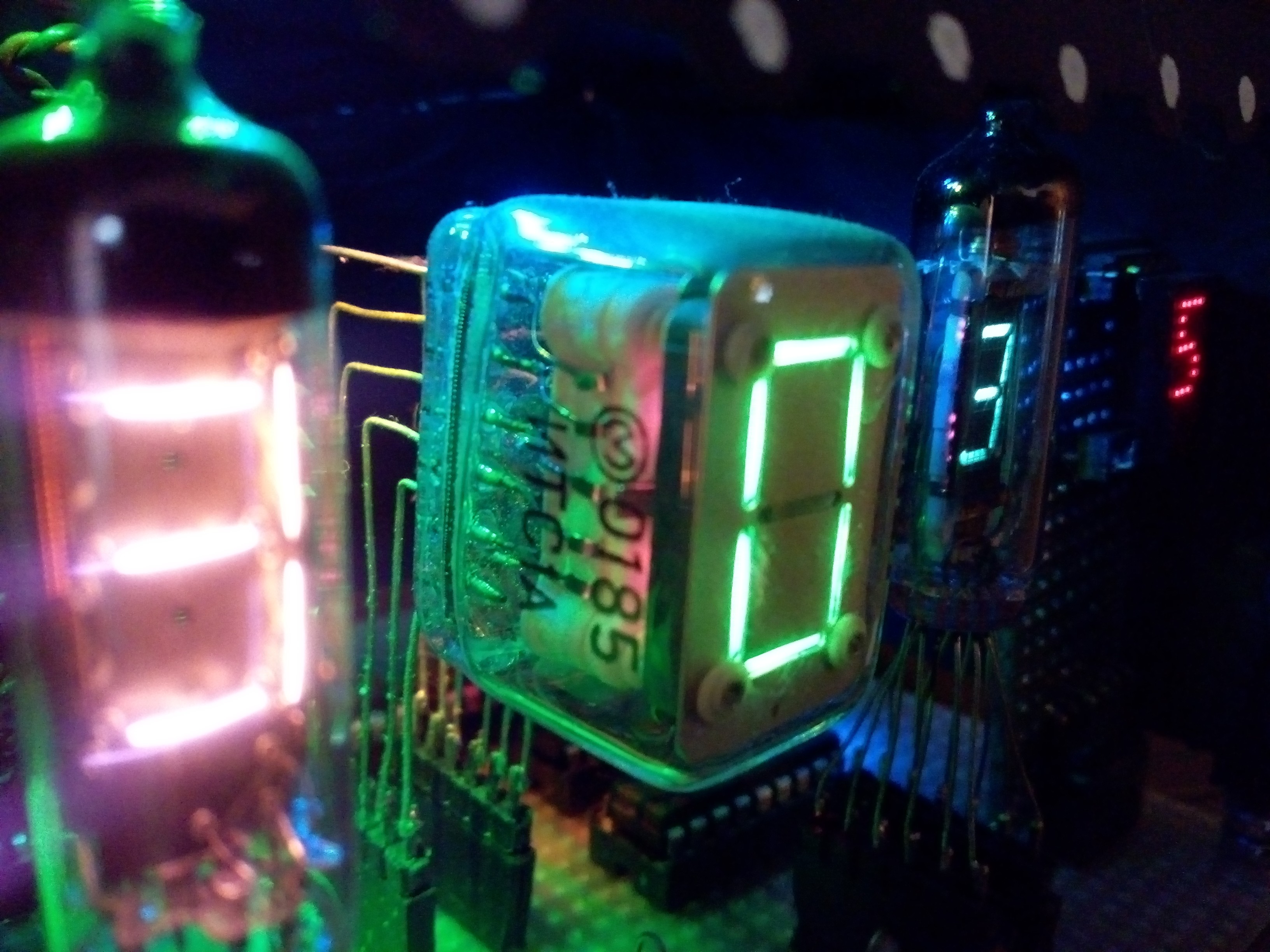
The magic glow of the thyratron inside of the ITS1A. You can see three different colours inside this tube.
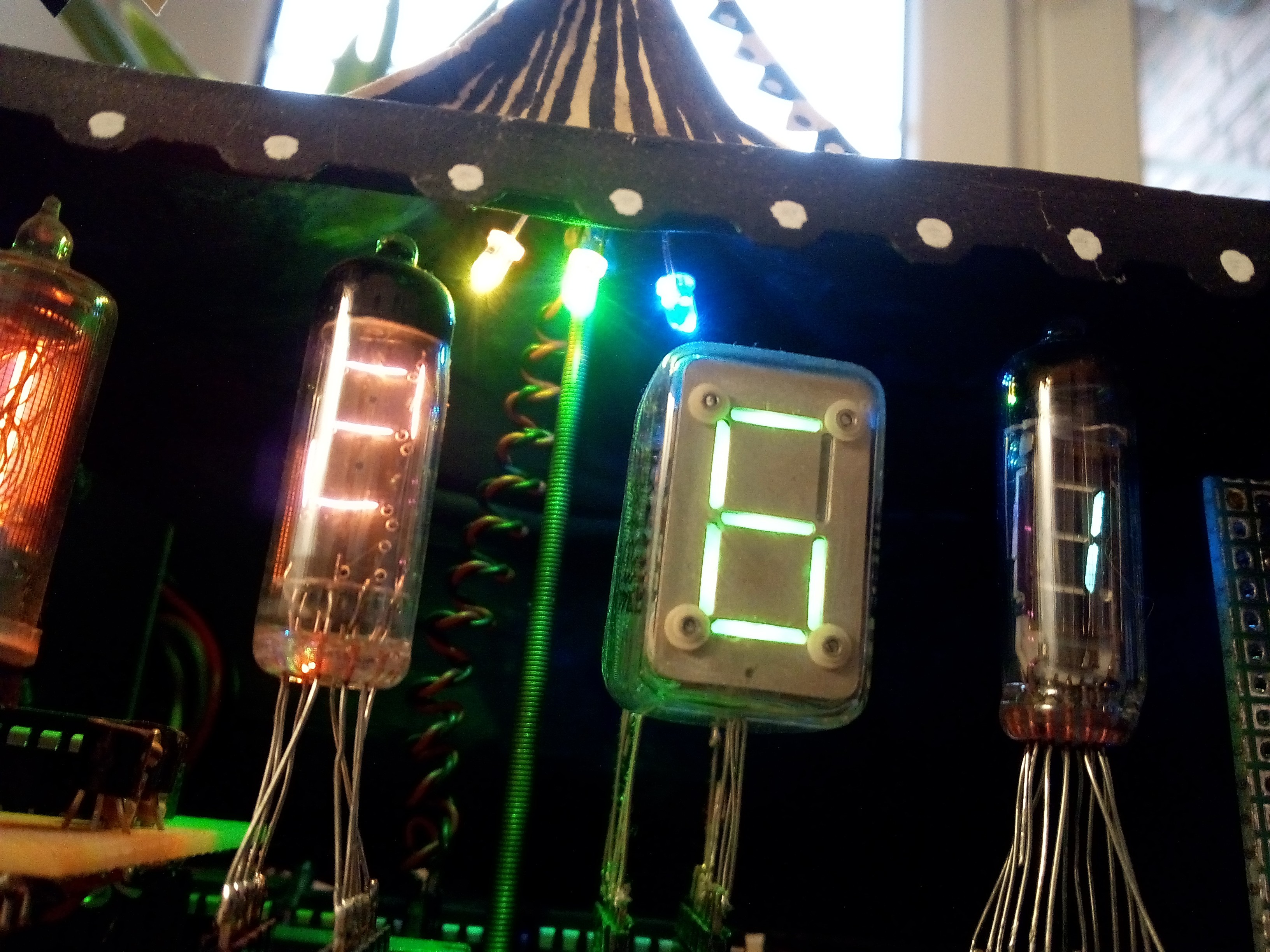
Some RGB rainbow LEDs make more “circus” inside the tent.
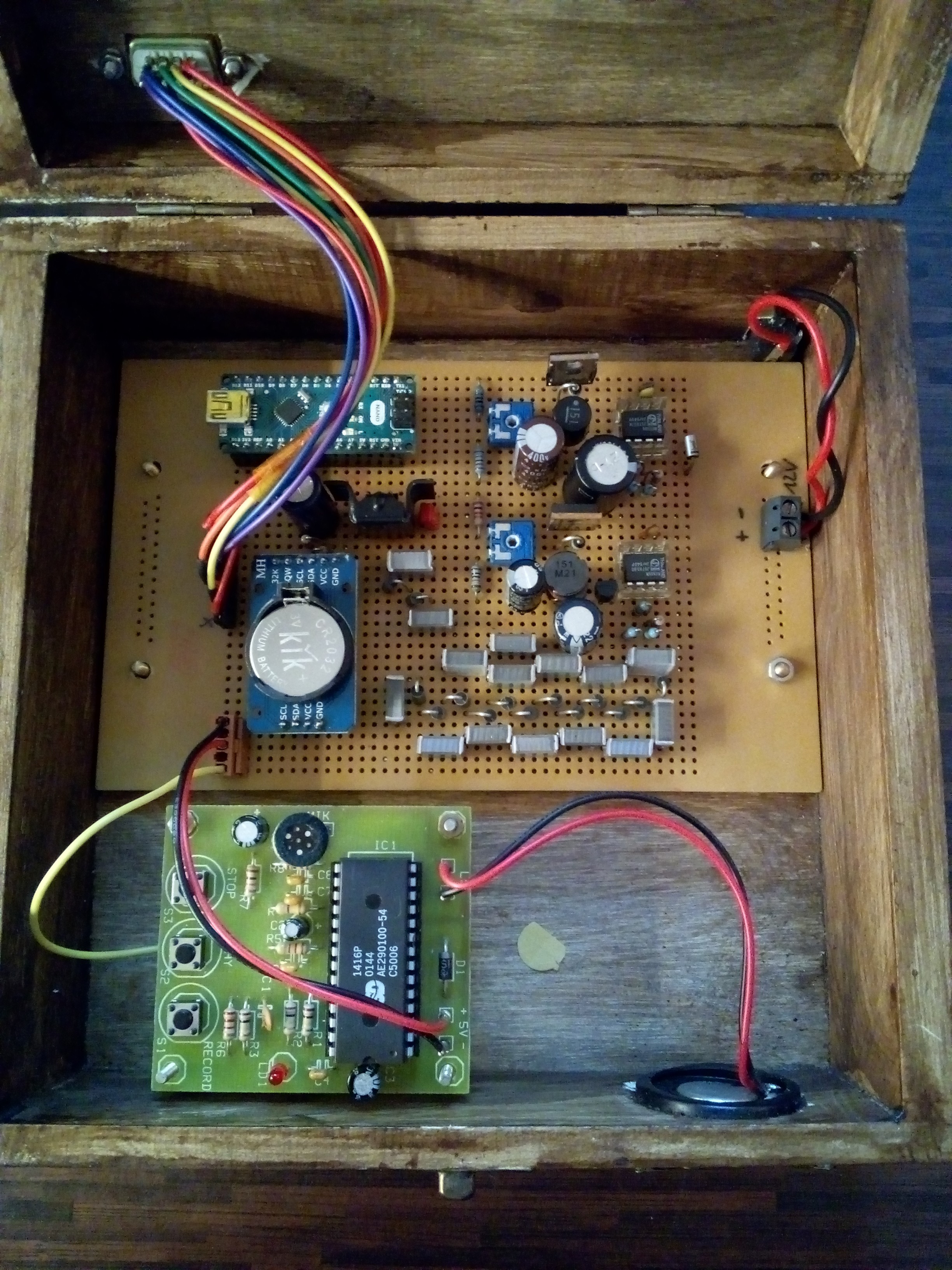
Inside the box. The upper PCB consists of the Arduino Nano, the boost converter and voltage multipliers. The green PCB is the sound recorder module with the ISD1416P. A power and pin 5 connector to the main PCB is visible also the wires to the little speaker. The coin cell powers up the RTC3232. Clearly visible is a single confetto (yellow) on the ground of the box. Circus!
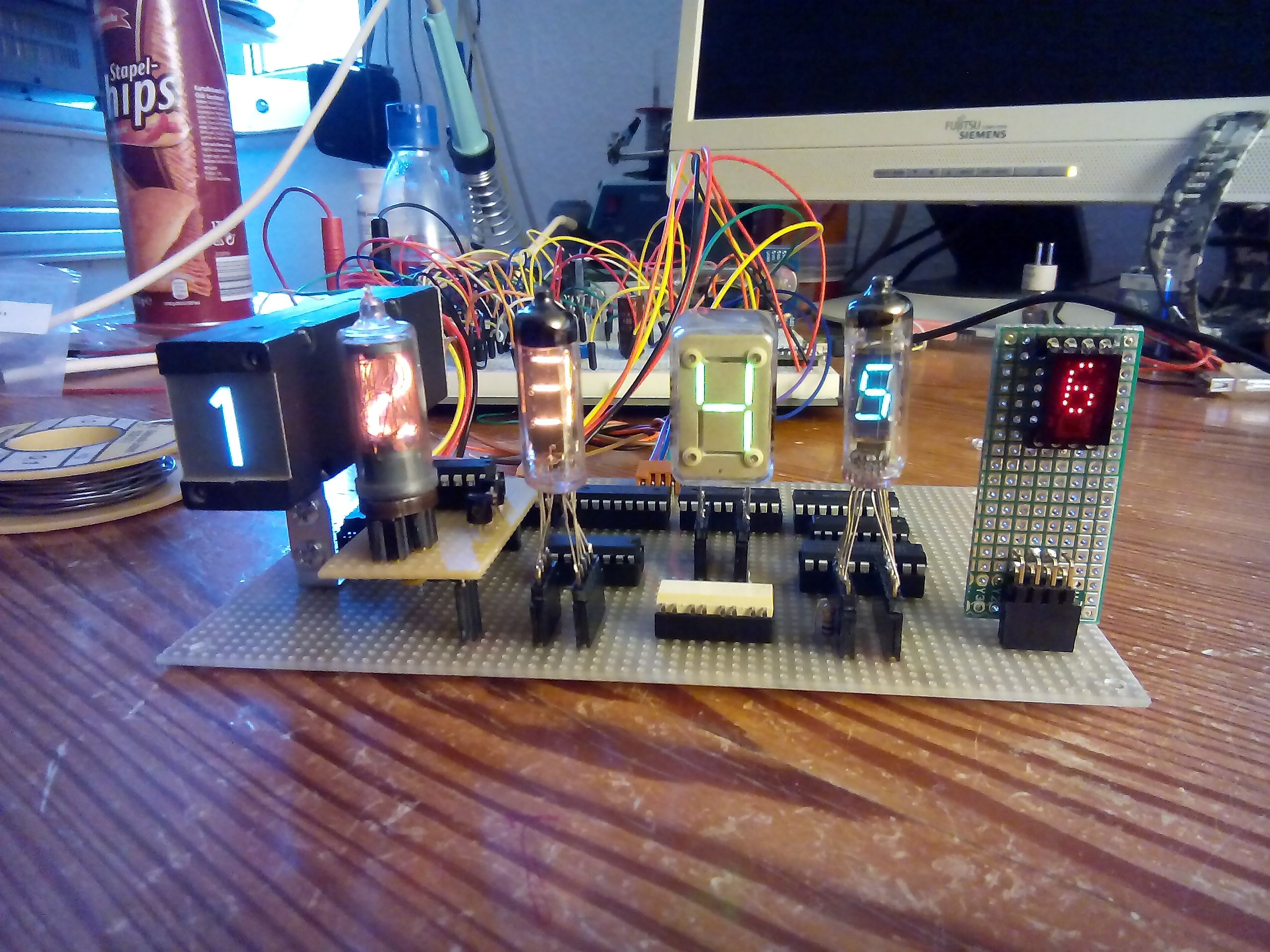
Testing, testing, testing... The power circuit is visible behind on a bread board. The micro USB for coding and debugging on the running system is shown on the right side in the background.
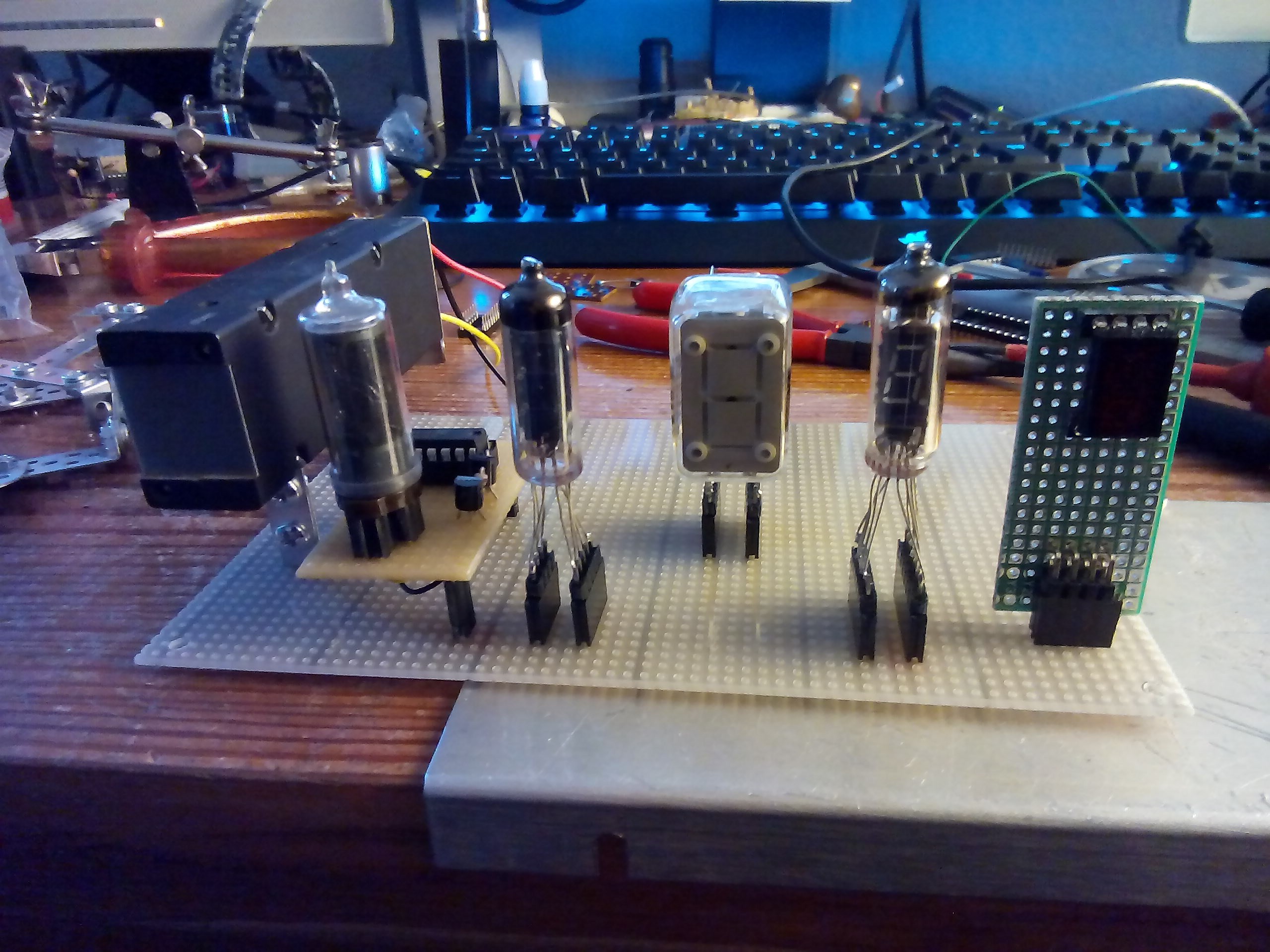
Everything finds the right place…after hours of shuffling the components.
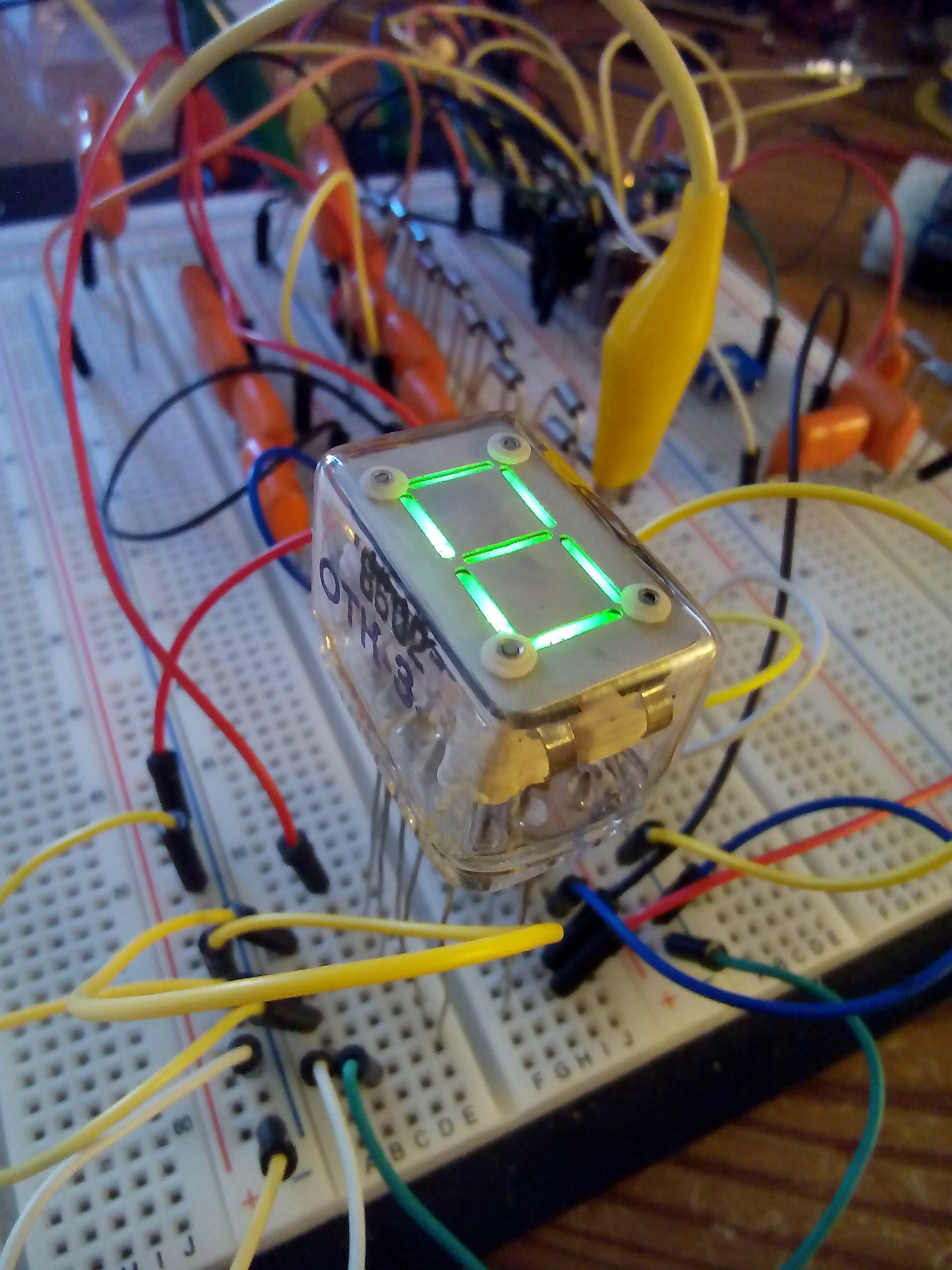
Heureka! The first light was coming out of this magic glass cube.
 Soldering...
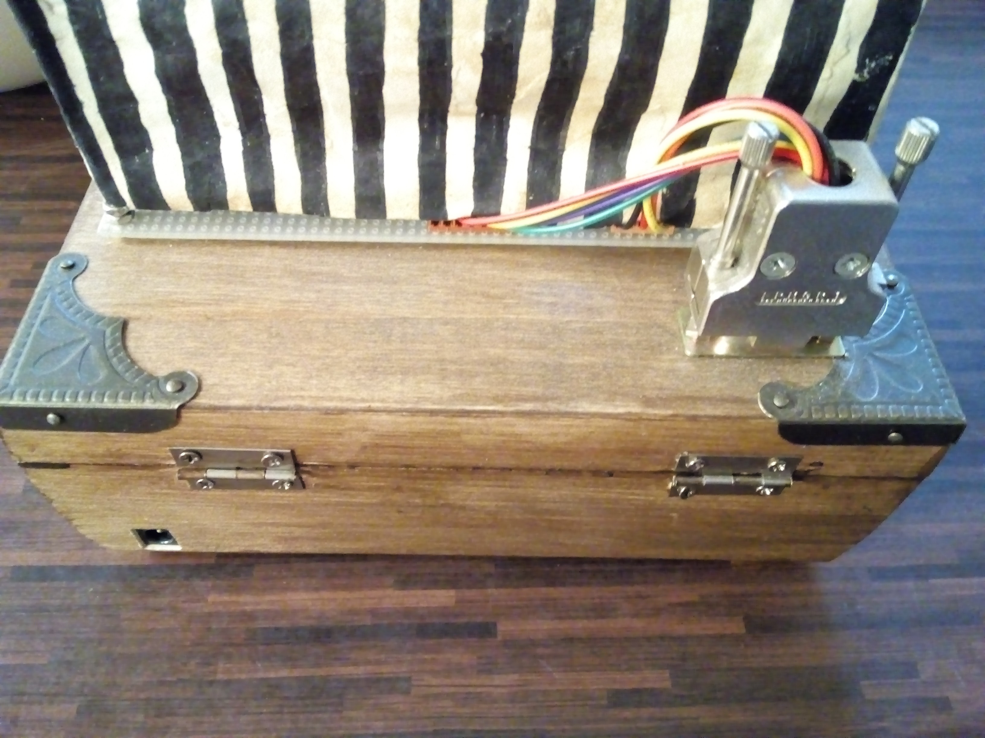 The back of the clock.
Code:
I am not a coding guy. It works for me. But see yourself. The code was written for the Arduino Nano:
#include <TimeLib.h>
#include <DS3232RTC.h>    //http://github.com/JChristensen/DS3232RTC
#include <Time.h>         //http://www.arduino.cc/playground/Code/Time
#include <Wire.h>         //http://arduino.cc/en/Reference/Wire (included with Arduino IDE)
int sekunda;
const int soundPin = 5;

void setup(void)
{
  Serial.begin(9600);
  Wire.begin(); //creates a Wire object
  pinMode(10, OUTPUT);
  MCPs_init();

pinMode(soundPin, OUTPUT);

  setSyncProvider(RTC.get);   // the function to get the time from the RTC
  if (timeStatus() != timeSet)
    Serial.println("Unable to sync with the RTC");
  else
    Serial.println("RTC has set the system time");
  // Set Time Block ...nach dem erstmaligen Hochladen wieder löschen.

  //the setTime() function is part of the Time library.
  //setTime(10, 39, 00, 31, 12, 2017);   //set the system time to 23h31m30s on 13Feb2009
  // RTC.set(now());                     //set the RTC from the system time

}

void loop(void)
{
  digitalClockDisplay();
  int stunde = hour();
  int minuta = minute();
  int secunda = second();
  int tag = day();
  int monat = month();
  long jahr = year();

  if (secunda >= 40 && secunda <= 47) {
    writeMCP(32, (((tag / 10) + ((tag % 10) * 16))));
    writeMCP(33, (monat / 10));
    writeITS(monat % 10);
    writeMCP(36, ((jahr - 2000) / 10) + (((jahr - 2000) % 10) * 16));
  }
  else {
    writeMCP(32, (((stunde / 10) + ((stunde % 10) * 16))));
    writeMCP(33, (minuta / 10));
    writeITS(minuta % 10);
    writeMCP(36, (secunda / 10) + ((secunda % 10) * 16));
  }
  if (secunda == 0 && minuta == 0) { //
    digitalWrite(soundPin, HIGH);
    delay (10);
    digitalWrite(soundPin, LOW);
  }

  delay(100);

}
//************************************ VOIDS **********************************
void writeITS(int counter) { // ONLY FOR ITS

  switch (counter) {
    case 0:
      writeMCP(34, 64);
      refresh_ITS();
      break;
    case 1:
      writeMCP(34, 121);
      refresh_ITS();
      break;
    case 2:
      writeMCP(34, 36);
      refresh_ITS();
      break;
    case 3:
      writeMCP(34, 48);
      refresh_ITS();
      break;
    case 4:
      writeMCP(34, 25);
      refresh_ITS();
      break;
    case 5:
      writeMCP(34, 18);
      refresh_ITS();
      break;
    case 6:
      writeMCP(34, 2);
      refresh_ITS();
      break;
    case 7:
      writeMCP(34, 120);
      refresh_ITS();
      break;
    case 8:
      writeMCP(34, 0);
      refresh_ITS();
      break;
    case 9:
      writeMCP(34, 16);
      refresh_ITS();
      break;
  }
}

void refresh_ITS() {
  digitalWrite(10, LOW);
  delay(3);
  digitalWrite(10, HIGH);
}

void writeMCP(int Addr, int Val) {
  Wire.beginTransmission(Addr); //starts talking to slave device
  Wire.write(0x09); //selects the GPIO pins
  Wire.write(Val); // turns on pins 0 and 1 of GPIOA
  Wire.endTransmission(); //ends communication with the device
}

void MCPs_init() {
  Wire.beginTransmission(32); //begins talking to the slave device
  Wire.write(0x00); //selects the IODIRA register
  Wire.write(0x00); //this sets all port A pins to outputs
  Wire.endTransmission(); //stops talking to device

  Wire.beginTransmission(33); //begins talking to the slave device
  Wire.write(0x00); //selects the IODIRA register
  Wire.write(0x00); //this sets all port B pins to outputs
  Wire.endTransmission(); //stops talking to device

  Wire.beginTransmission(34); //begins talking to the slave device
  Wire.write(0x00); //selects the IODIRA register
  Wire.write(0x00); //this sets all port C pins to outputs
  Wire.endTransmission(); //stops talking to device

  Wire.beginTransmission(36); //begins talking to the slave device
  Wire.write(0x00); //selects the IODIRA register
  Wire.write(0x00); //this sets all port D pins to outputs
  Wire.endTransmission(); //stops talking to device
}
void digitalClockDisplay(void)
{
  // digital clock display of the time
  Serial.print(hour());
  printDigits(minute());
  printDigits(second());
  Serial.print(' ');
  Serial.print(day());
  Serial.print(' ');
  Serial.print(month());
  Serial.print(' ');
  Serial.print(year());
  Serial.println();
}

void printDigits(int digits)
{
  // utility function for digital clock display: prints preceding colon and leading 0
  Serial.print(':');
  if (digits < 10)
    Serial.print('0');
  Serial.print(digits);
}