 Mark Rehorst
When it comes to 3D printers, I'm sort of old-school. I believe the machine should be made solid, and surfaces that are supposed to be flat should be flat- bed surfaces doubly so. A lot of printers use leveling screws at the 4 corners of the bed even though a bed is supposed to be a plane, and it only takes 3 points to define a plane. 4 screws will cause either or both the bed plate and the carriage plate to bend, so I use 3 screws.
I've been experimenting with and refining my 3 point bed support for a few years and believe the bed I used in my latest printer, Ultra MegaMax Dominator (UMMD) is about as good as I'll ever be able to make it.
Kinematic mounts are commonly used to mount lenses and beam splitters on optical tables. They constrain six degrees of freedom while allowing very stable positional adjustments. When applied to a 3D printer bed, they also allow the bed to expand when heated without causing any forces that might flex either the bed or the support structure.
UMMD's bed uses such a kinematic mount that I detailed on a blog page here.

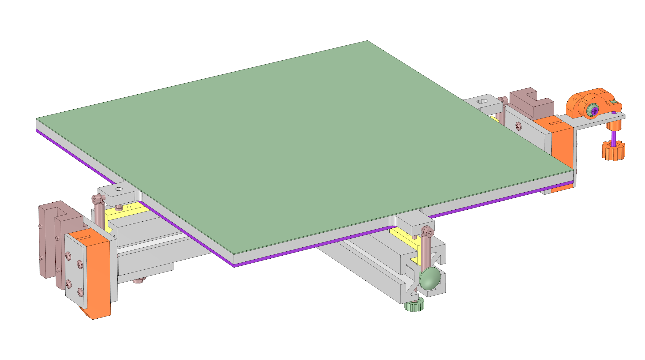
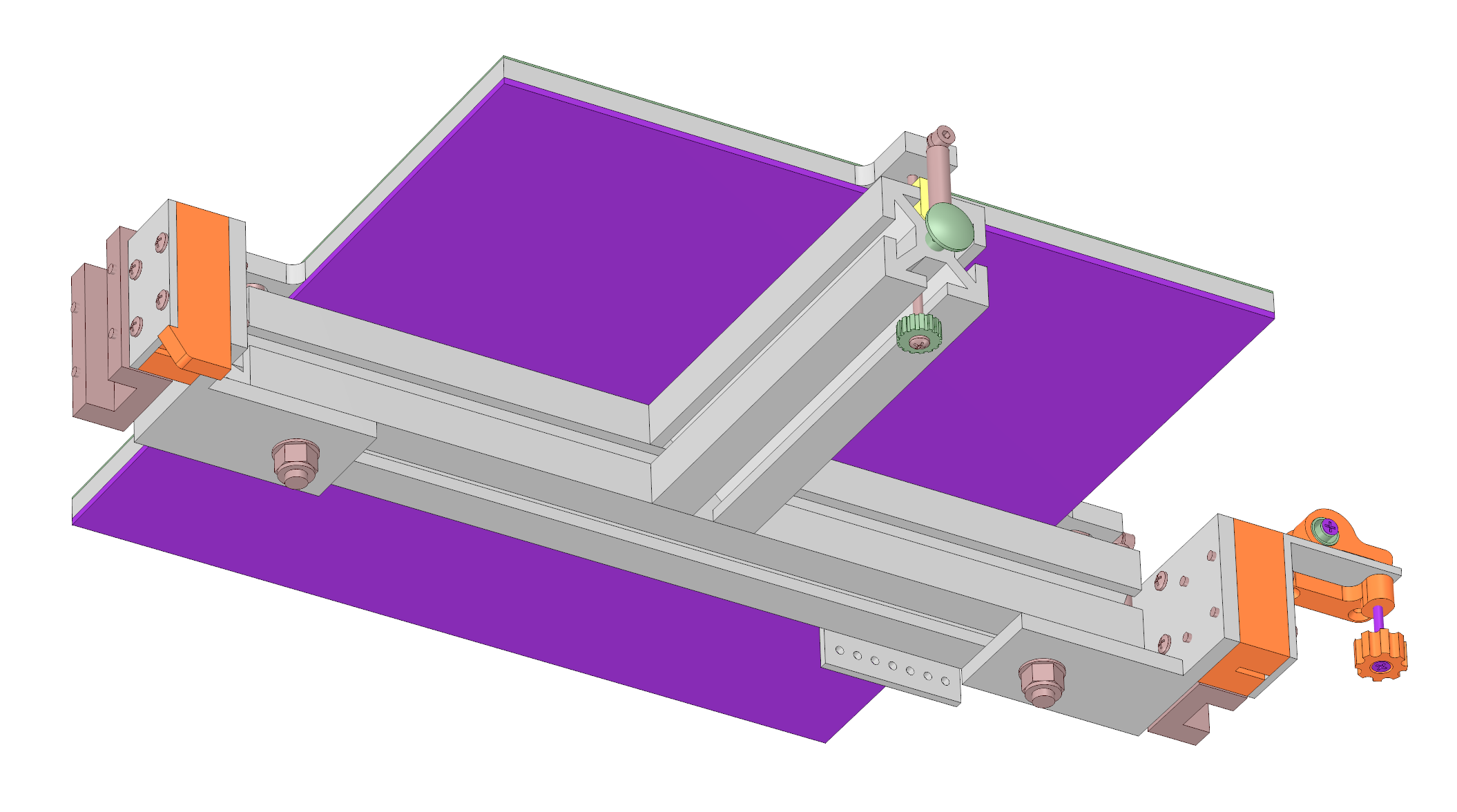
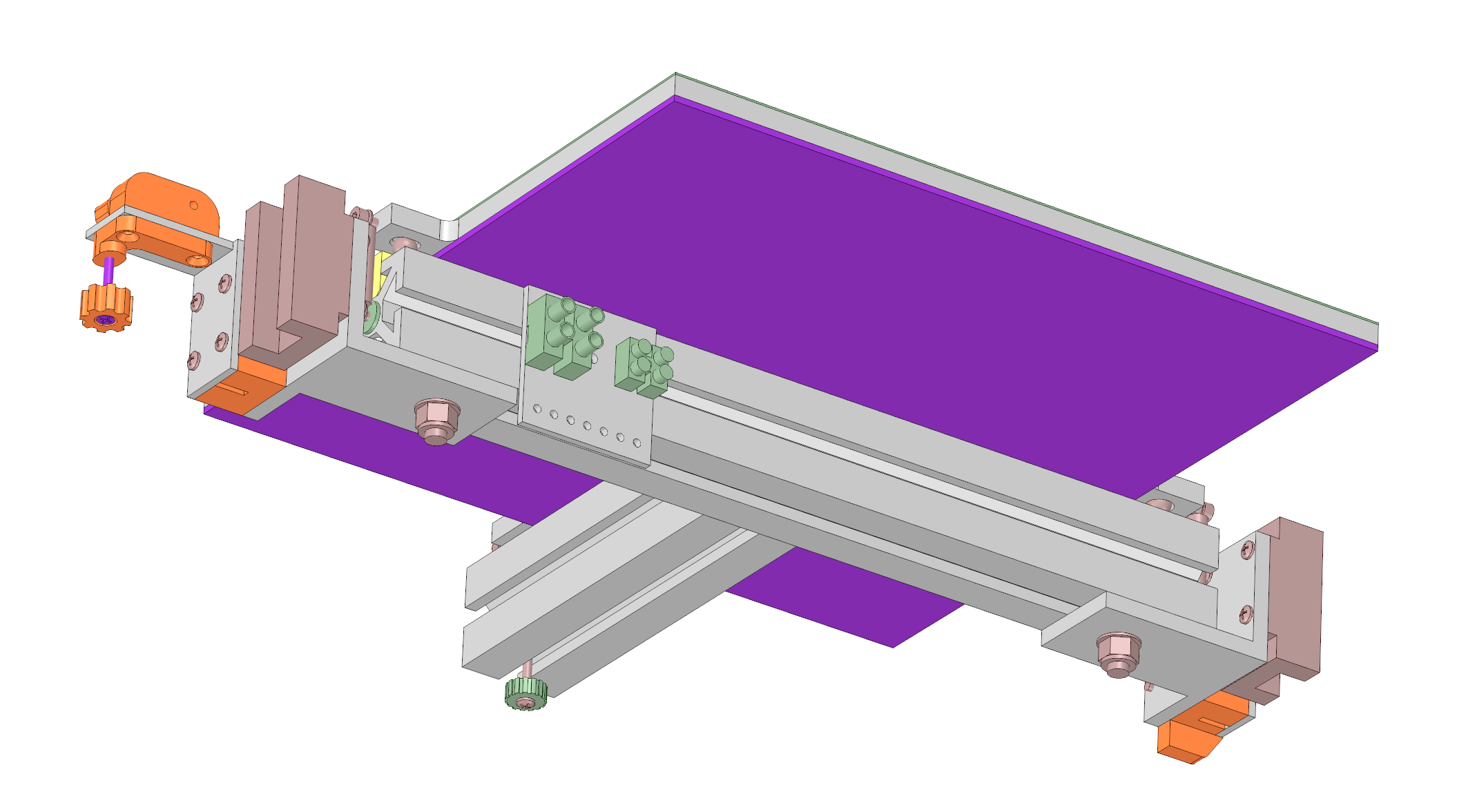
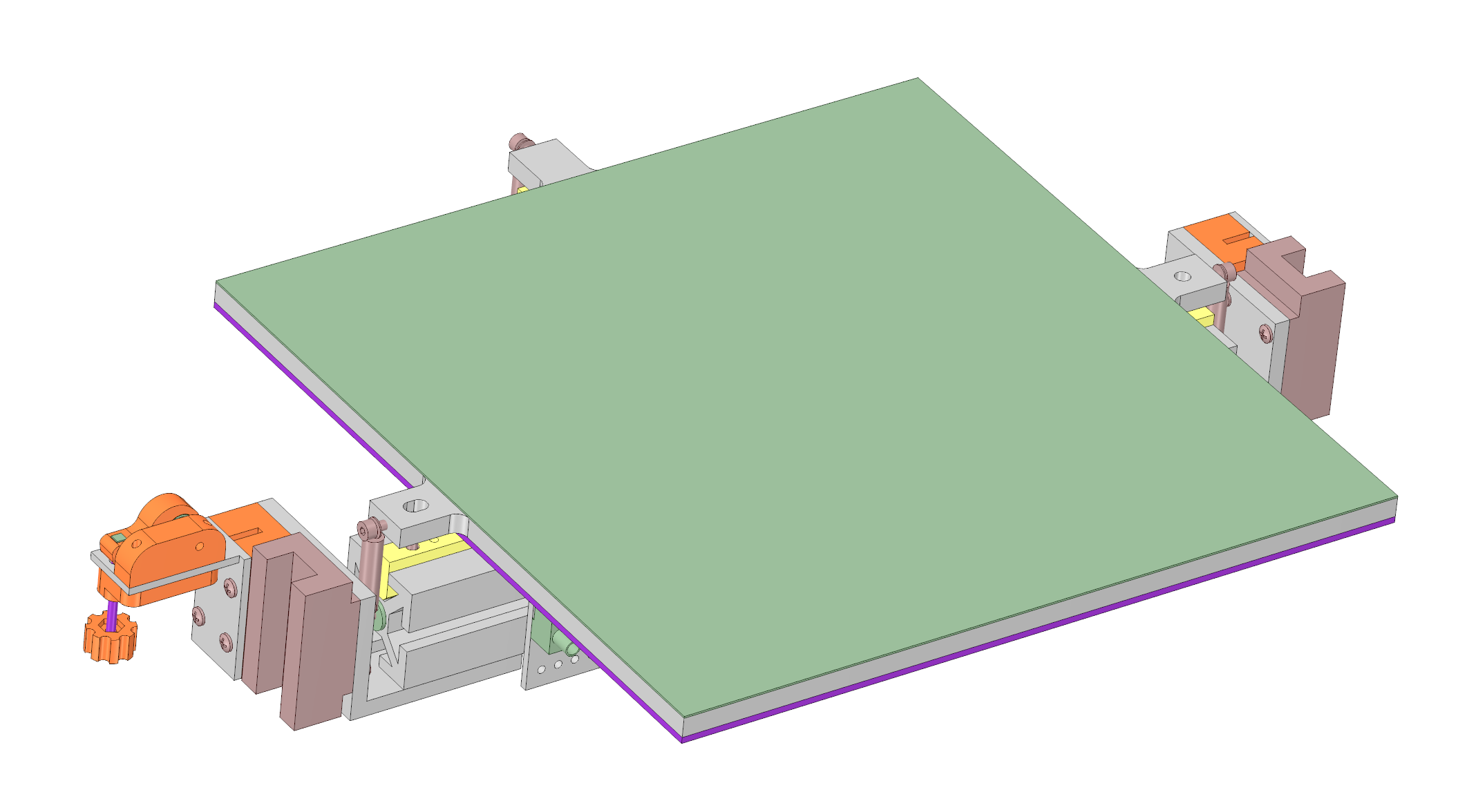
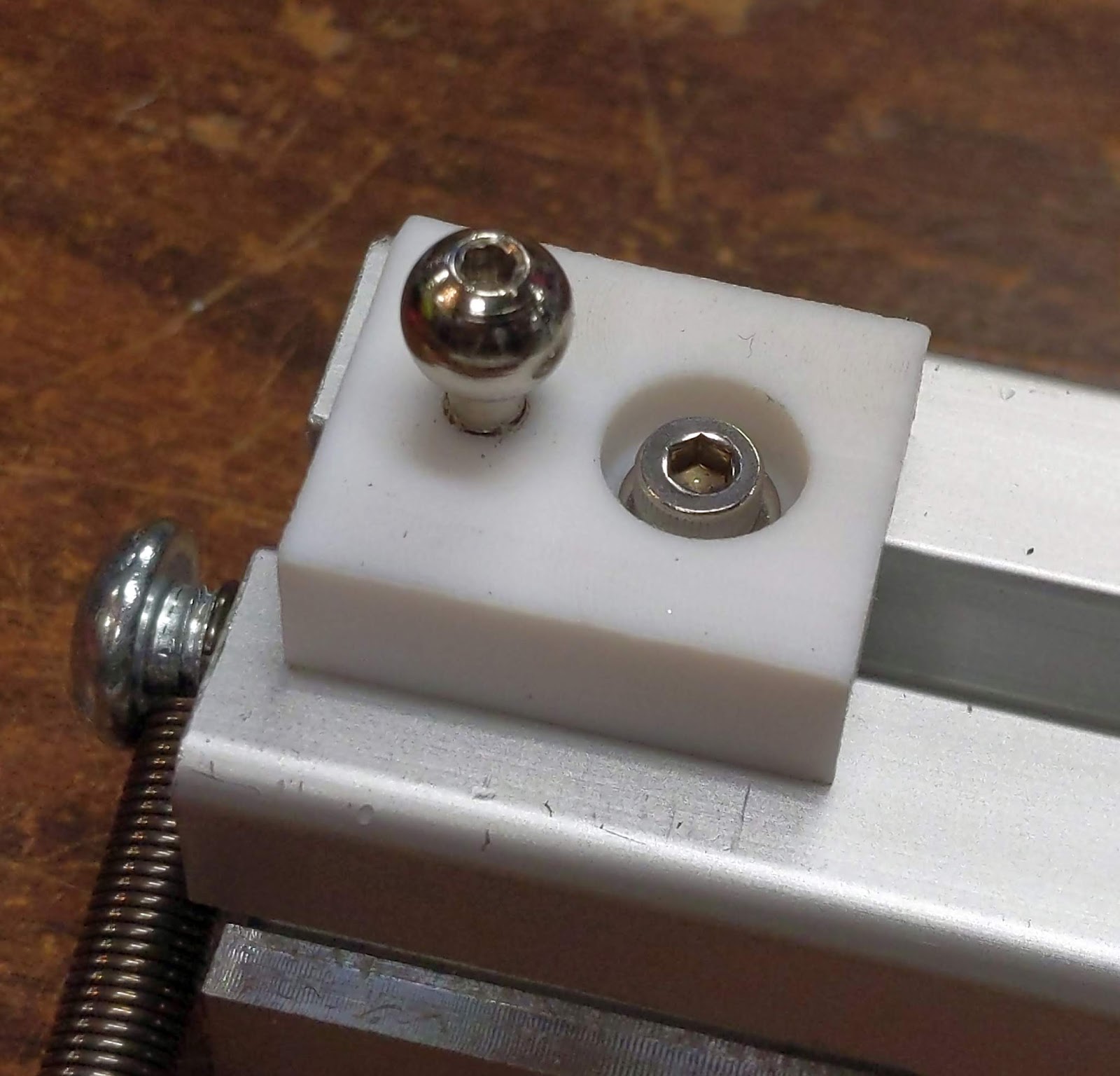
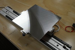
The three leveling screws mount in heat tolerant Teflon or Torlon blocks (yellow, below) screwed to the bed support structure. The leveling screws roll their own threads into the plastic so they are gripped tightly and don't wobble. The reference and pitch adjuster screws are turned from the top side of the bed. The reference screw sits in a chamfered hole that allows rotation and tilt for leveling adjustments. The pitch adjuster, sitting in a chamfered slot on the opposite side of the bed, stops rotation at the reference screw but allows tilt and thermal expansion. The roll screw adjusts from below and and just contacts the flat surface of the bed. That allows the bed to tilt when leveling and for thermal expansion. The bed plate is held down onto the screws by springs adjacent to each. The bed is topped off with a 30 mil (0.7 mm) layer of PEI (green, below). Nothing stands up above the bed surface, so there's no chance of crashing the extruder nozzle into anything.
In this type of arrangement you adjust the pitch first, then the roll, a process that takes all of 1 minute if you're extra careful. The structure is so stable I haven't had to adjust it since the last time I took the bed apart about 4 months ago.
The bed is heated with a 750W, line powered heater (purple, above) that gets it up to ABS print temperature of 105C in about 4.5 minutes. An SSR switches power under PID control from the SmoothieBoard controller. I added a thermal cutoff to protect against failure of the SSR (they fail shorted), and an electrical fuse to protect against wiring failures. The printer's frame is grounded to the power line ground.


 heinz
heinz
 Dylan Radcliffe