This project wouldn't be complete with instructions on how to set up your own MQTT broker. The MQTT broker is a piece of software, running on a server somewhere in the world (ideally in your own house) where the RGB LED Matrix connects to. The server generates a 32x32 pixel image and sends it to the matrix which displays it.
This log summarises how I set up my server. If you want to learn more about the MQTT protocol I highly suggest this website. However, as far as this project is concerned, you don't need any other prior knowledge than the ability to follow a numbered list:
I used a Raspberry Pi 2 (RPi) to set up the MQTT broker, the RPi hardware version does not really matter for this project as any version can handle the software we're about to install. The purpose is to have an "always-on" tiny computer to update the display.
I like to set up my headless RPis with Diet-Pi distribution in favour of Raspbian. It offers some advantages over the Raspbian Lite (memory, tuning, responsiveness, space usage...). Diet-Pi also makes it easy to install optimised versions of the required packages.
Once the RPi is installed and configured to connect to the local access point it's ready to get the Mosquitto broker and the Node-RED front end:
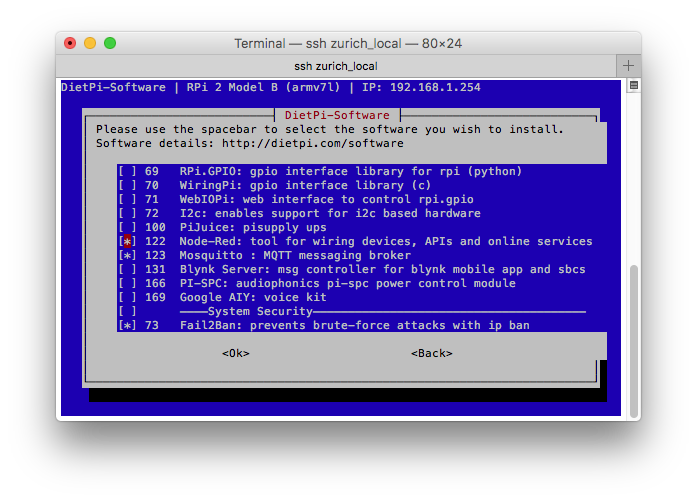
Type dietpi-software into the command line to get access to the RPi optimised software packages.
Select "Software Optimised".
Check the Node-Red and Mosquitto packages with space bar:
Press "Enter" to get back to the main menu.
Scroll down to "Install" and wait for the system to finish installing the packages.
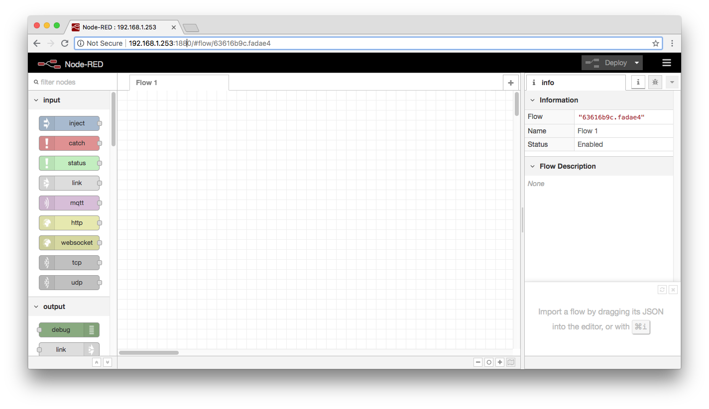
You now have a fresh install if Node-RED that is ready to talk to your Mosquitto broker and exchange messages. Using your web browser navigate to the IP of your RPi on port 1883, for me it is 192.168.1.253:1883. You should see something resembling the following:
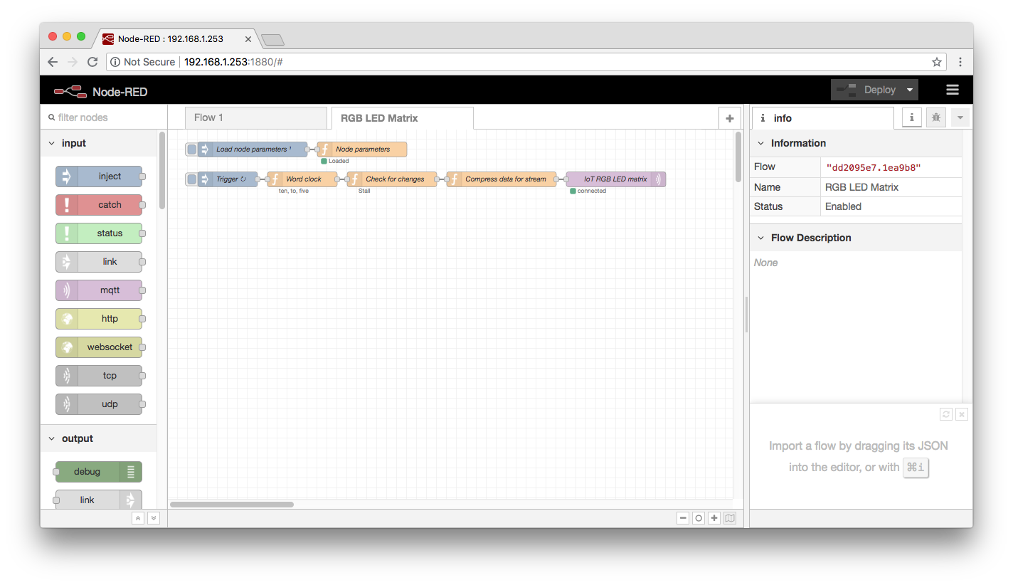
It is time to start building the display script. However, I don't expect anybody to have JavaScript skills, so instead simply import the Node-RED "flow" I have prepared. From the right top corner click on "Import" and select "Clipboard". Paste the contents of "rgb_led_matrix_wordclock.js" inside it and press the "Import" button.
You should see the following new flow in the Node-RED front end:This flow will publish a new message every minute with a topic named "display", this is the topic name the ESP32 should be configured to listen to for this system to work. Click the "Deploy" button for the flow to start.
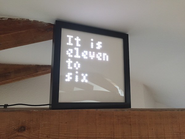
If you have properly configured your RGB LED Matrix, with the proper access point credentials, IP of the RPi and topic name of the message, then it should be able to receive the messages published by this flow:
You can modify, explore, add all sorts of flow items. Even make flows send messages between themselves. Node-RED is very versatile and graphic aspect allows to visually organise the message flows. Have fun displaying your own data.
Discussions
Become a Hackaday.io Member
Create an account to leave a comment. Already have an account? Log In.