Close
0%
0%

Analog Touch Control Business Card

Touch controlled light-up PCB business card, no microcontroller required!

Similar projects worth following
While I had seen other examples of PCB business cards before, most of them either had no circuitry or focused on IC laden microcontroller-based circuits. For my card, I wanted to take a middle route which took advantage of the aesthetic possibilities of PCB design while demonstrating some novel electrical functionality.In addition, it so happened that the Coin Cell Challenge launched just as I was finishing the first batch of cards. While this card doesn't have the bang or panache for the Supernova or Heavy Lifting awards, I'd wager it has the potential to power the longest-lived project of all: a lifelong career in engineering. And all with a single CR2032 coin cell.Design files are on Github at https://github.com/AG6GR/BusinessCard

Design Process

Brainstorming

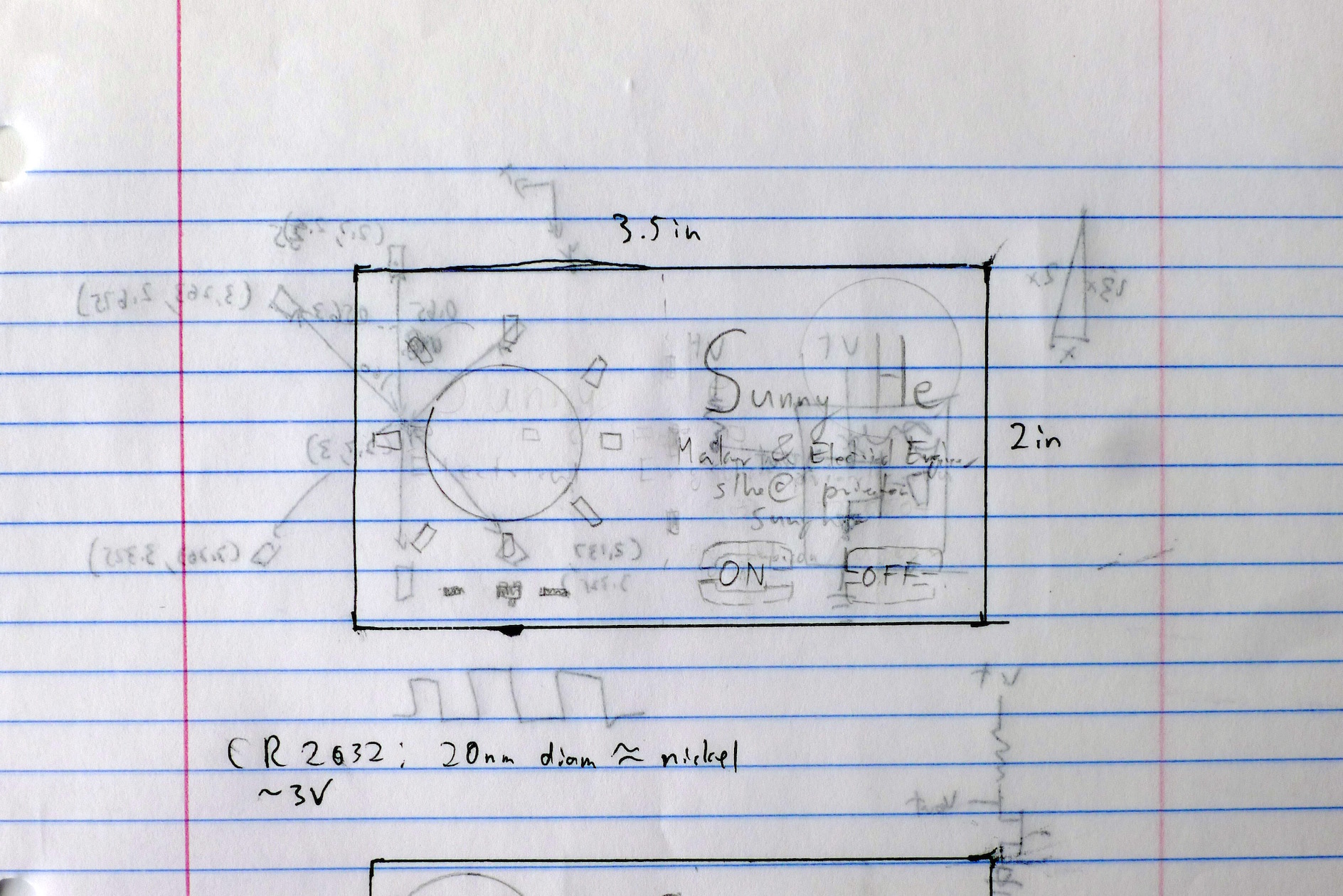
I performed the inital brainstorming and rough design on paper, mocking up different options with pencil in a ink 3.5x2" rectangle. I had the idea for the MOSFET-based touch circuit from earlier work, but there were some special design contraints to work with for this board.

  • Size: The board must be within the normal business card size of 3.5x2", and be low-profile enough to carry around
  • Components: While surface-mount components were mandatory to reduce the thickness of the card, I didn't have access to a reflow oven. To ease hand-soldering, all components had to be at least 1206.
  • Simplicity: Use as few components as possible and avoid IC's.
  • Clarity: My name and contact information had to be prominently featured. This is a business card after all.
  • Aesthetics: It had to look good.

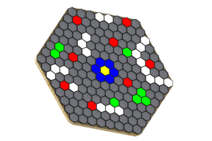
I eventually settled on a star formation of LED's arranged around the battery, taking advantage of the dominating circular form to evoke a classic star or "sun" shape.

Inkscape Mockup

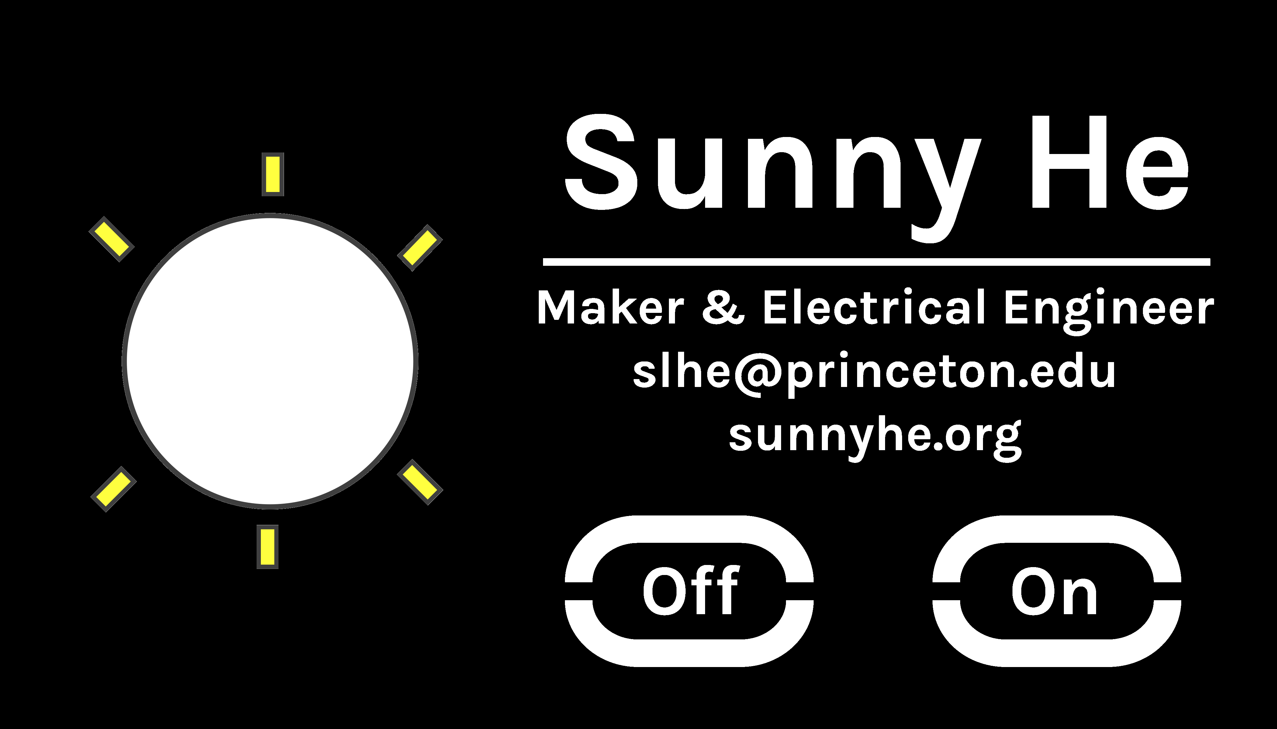
Next the design was finalized in Inkscape as an SVG vector file. I used the Google Fonts tool to find the Karla font used for all the lettering.

PCB Layout

PCB Layout

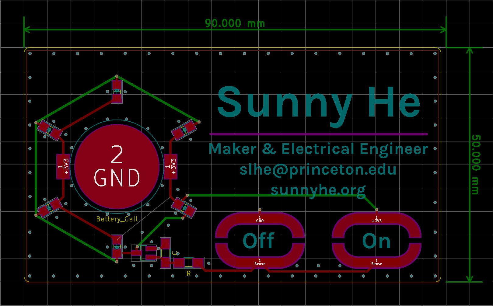
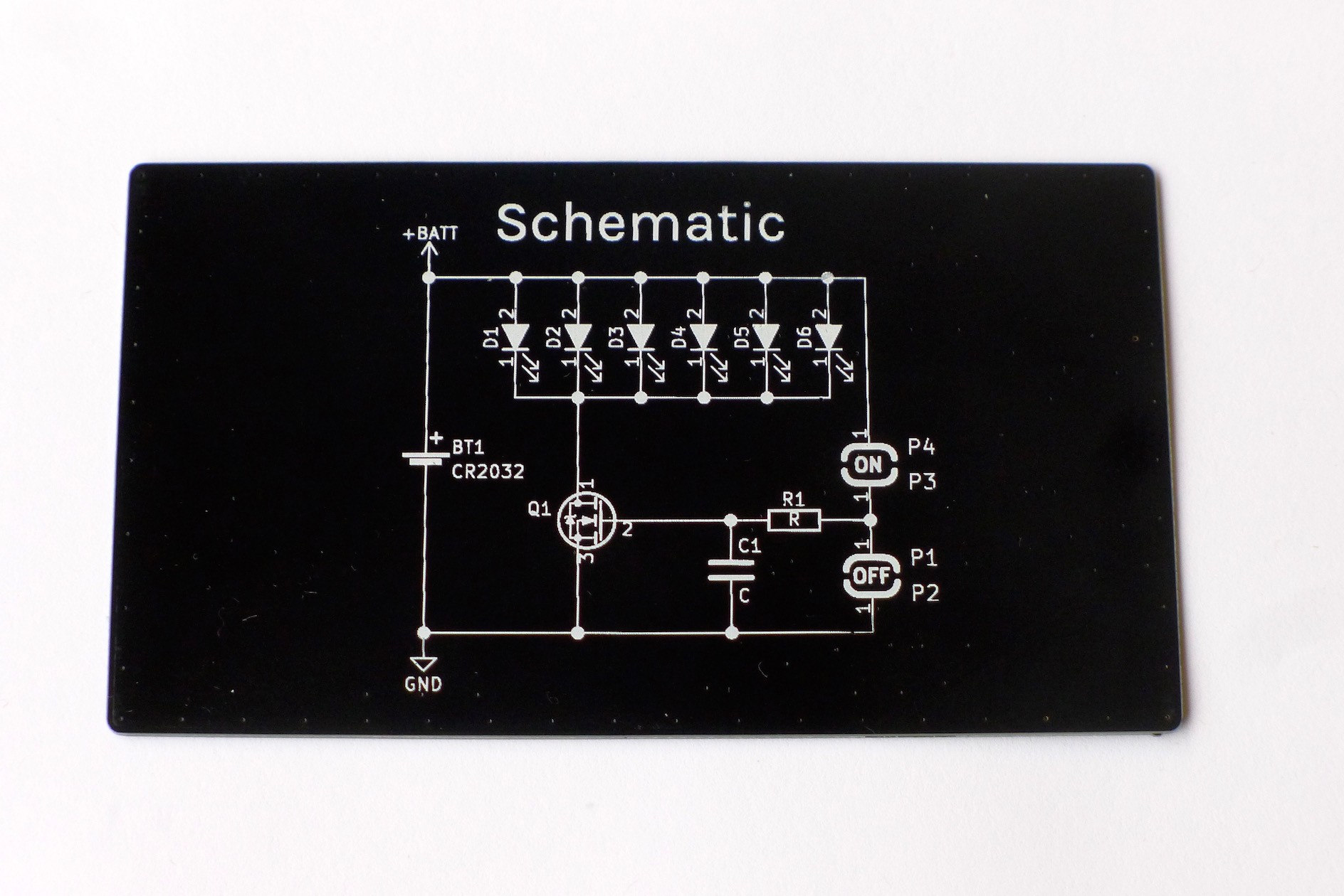
The rest of the board layout was performed in KiCAD. Silkscreen elements were directly converted into KiCAD components using the svg2mod tool. The touch pads were individually made into their own components in order to properly define pads and solder mask. The image of the schematic on the rear was created by plotting an SVG representation of the schematic from KiCAD, then cleanup and conversion to a PNG in Inkscape, followed by importing via the bitmap2component tool in KiCAD. The svg2mod tool had difficulty with the thin lines in the schematic, and bitmap conversion proved to give a much better result. I also resized the board slightly, to 50x90mm.

Manufacture and Assembly

Bare Board

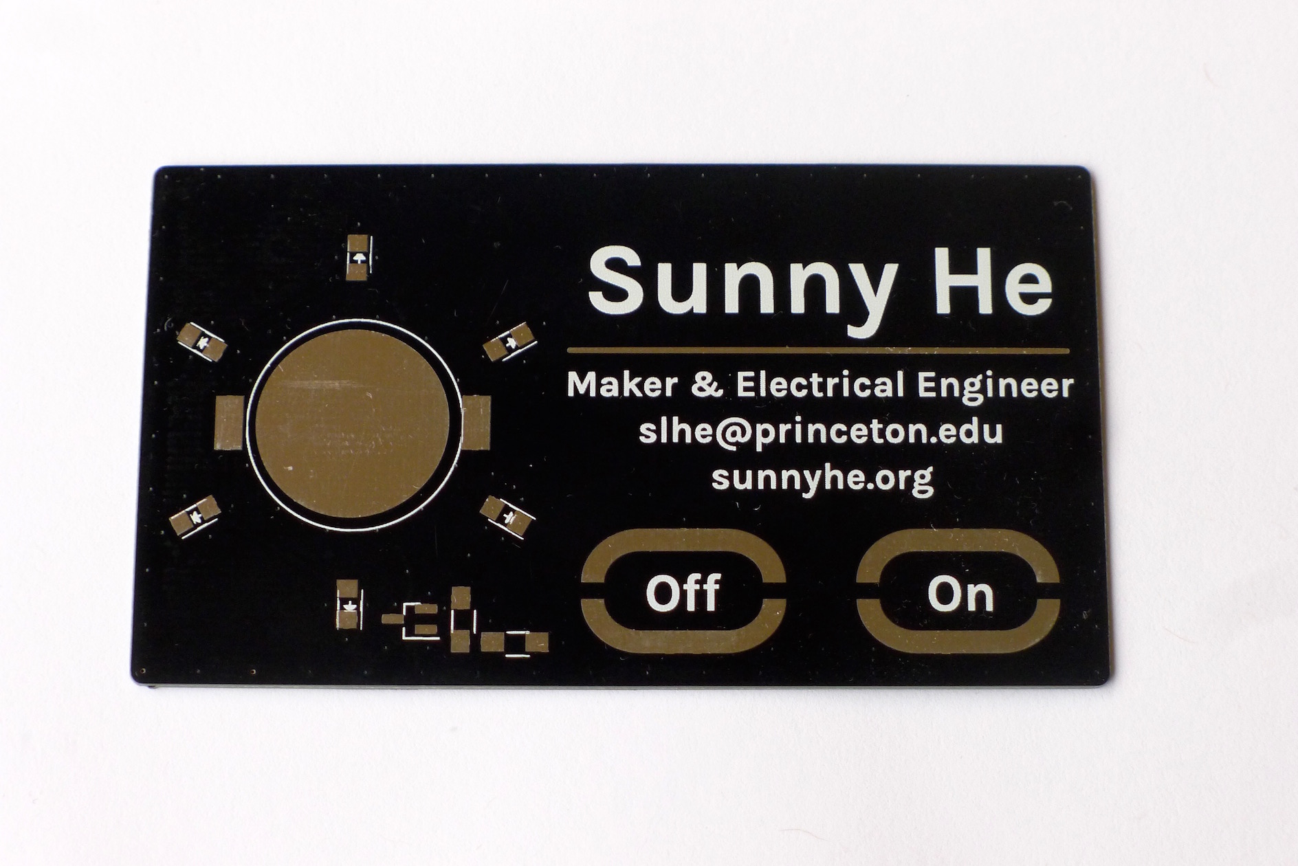
I ordered ten boards from Elecrow's PCB service, choosing a black soldermask and 0.6mm thickness. With DHL shipping ($17.04), the total price came out to $28.54. Elecrow has a nice habit of sending extra boards, so I ended up with 11 boards at a cost of $2.59 each.

From there on out, all the boards were hand assembled. Because my hands are absurdly unsteady, I used Scotch tape to position and hold down components before soldering. Even though this was probably an extreme ESD hazard, most of the components were simple passives anyway and everything worked out alright. In hindsight, assembly took so long that it might be worth subcontracting assembly out to a small batch company for future runs.

business_card.gif

The card in action

Graphics Interchange Format - 909.13 kB - 01/01/2018 at 20:33

Preview
Download

  • 6 × Yellow LEDs Lite-On LTST-C150KSKT
  • 1 × N-Channel MOSFET ON/Fairchild FDV301N
  • 1 × 1KΩ Resistor Yaego RC1206FR-071KL
  • 1 × Battery Holder Linx Technologies BAT-HLD-001
  • 1 × CR2032 Coin Cell Panasonic CR2032

View all 6 components

  • Circuit Analysis

    Sunny01/01/2018 at 21:00 0 comments

    While the circuit may seem quite simple, it takes advantage of a number of non-ideal characteristics to make touch control possible. The N-MOSFET acts as a standard low-side switch, turning the yellow LED's on and off. The CR2032 coin cell supplies 2.8-3.0V, and its own internal resistance provides current limiting for the LED's.

    The touch pads rely on skin conductivity to charge up the gate capacitance of the MOSFET. This capacitance is indicated as C1 on the schematic. Once the voltage exceeds the MOSFET turn on voltage, the MOSFET begins conducting and the LED's turn on. While for most purposes skin may seem like an insulator, people are surprisingly conductive. Some quick work with a multimeter showed most people's fingers seemed to be range between 10 and 20 MOhm. The MOSFET on the board also isn't an ideal component. There is a small but still significant capacitance between the gate and source of the MOSFET. In the case of the FDV301N MOSFETS used on this board, the input capacitance is specified to be about 9.5pF.

    When a person bridges one pair of touch pads with their finger, this forms an RC circuit with a time constant of about 0.1-0.2 milliseconds. Pressing on the "ON" button charges the gate capacitance, turning the MOSFET on, while pressing the "OFF" button discharges the gate capacitance, turning the MOSFET off. A series resistor is added on the input line to help suppress stray induced currents, which would cause the LED's to flicker or turn on without being touched. The value is not critical, as long as it is relatively small compared to skin resistance. I also added pads for an extra capacitor to be added in parallel to the MOSFET's gate capacitance to tune the time constant, but ultimately this proved unnecessary.

View project log

Enjoy this project?

Share

Discussions

embeddedn8 wrote 01/07/2018 at 02:54 point

Nice project! I designed some PCB business cards which just arrived today. I'll be posting a project soon, mine is more complicated but I really like the simplicity of yours. Have you considered a resistor to limit the LED current? Clearly you're using the source impedance of the 2032 to limit the current but adding a small resistor in series with the paralleled LEDs would substantially increase the battery life. 

  Are you sure? yes | no

Sunny wrote 01/07/2018 at 05:22 point

Glad you liked it! Since I knew I had to hand solder the first run of boards, I really wanted to keep the number of components as low as possible. In the end, I didn't consider battery life to be a really important factor as long as it lit up nice and bright for the few minutes people were playing with the card. Even if the battery does run out, CR2032's are pretty common and the visual design holds up even without the lights on. Looking forward to seeing your business card!

  Are you sure? yes | no

Similar Projects

Does this project spark your interest?

Become a member to follow this project and never miss any updates