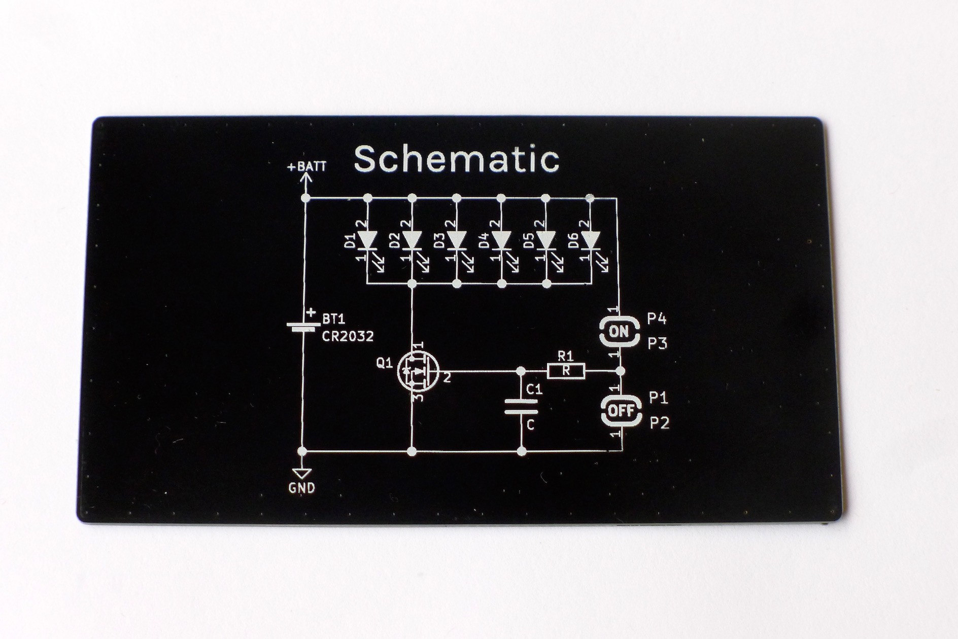
While the circuit may seem quite simple, it takes advantage of a number of non-ideal characteristics to make touch control possible. The N-MOSFET acts as a standard low-side switch, turning the yellow LED's on and off. The CR2032 coin cell supplies 2.8-3.0V, and its own internal resistance provides current limiting for the LED's.
The touch pads rely on skin conductivity to charge up the gate capacitance of the MOSFET. This capacitance is indicated as C1 on the schematic. Once the voltage exceeds the MOSFET turn on voltage, the MOSFET begins conducting and the LED's turn on. While for most purposes skin may seem like an insulator, people are surprisingly conductive. Some quick work with a multimeter showed most people's fingers seemed to be range between 10 and 20 MOhm. The MOSFET on the board also isn't an ideal component. There is a small but still significant capacitance between the gate and source of the MOSFET. In the case of the FDV301N MOSFETS used on this board, the input capacitance is specified to be about 9.5pF.
When a person bridges one pair of touch pads with their finger, this forms an RC circuit with a time constant of about 0.1-0.2 milliseconds. Pressing on the "ON" button charges the gate capacitance, turning the MOSFET on, while pressing the "OFF" button discharges the gate capacitance, turning the MOSFET off. A series resistor is added on the input line to help suppress stray induced currents, which would cause the LED's to flicker or turn on without being touched. The value is not critical, as long as it is relatively small compared to skin resistance. I also added pads for an extra capacitor to be added in parallel to the MOSFET's gate capacitance to tune the time constant, but ultimately this proved unnecessary.
Discussions
Become a Hackaday.io Member
Create an account to leave a comment. Already have an account? Log In.