Software used:
- MPLAB X IDE v.4.0.1
- MPLAB Harmony 1.07.01
- MPLAB XC32 1.44
Hardware used:
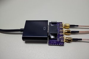
- PIC32MX250F128B
- Cytron SK1632
- PICkit 3
- DAC used:
- WM8731
- PCM5102
- UDA1334ATS
Note on hardware: You can also use a Digilent chipKIT DP32 but you have to backup the bootloader since this one doesn't use any bootloaders.

 Ted Yapo
 agp.cooper
 Bruce Land