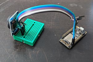
Close
0%
0%

Windy

A connected, multi-way fan controller with synchronization and temperature logging

Similar projects worth following
Windy is a many-way fan controller based on the ESP32 which aims to control up to 8 fans independently or in groups with speed/phase synchronization between fans in groups to reduce or modulate noise. It is remotely accessible and controllable via WiFi, Bluetooth and Ethernet (if I'm lucky). It logs temperature and fan data for later consumption by external applications.

Windy aims to be compatible with a broad selection of fans. It can work fine with standard 4-wire PWM fans (including some with non-standard controls, such as inverted PWM), but it also includes power switches and tachometer compensation for 3-wire and 2-wire fans. Windy targets fans pulling up to several amps at 12VDC.

Windy is still in the research phase; I have a general plan for the system and some of the lower-level components such as the power switch with tachometer compensation as well as the software for the control and synchronization of the fans, but very little has been actually executed in HW yet.

  • 1 × ESP32-WROOM ESP32 module (prototype only, bare chip for final)
  • 1 × MCP23017 Microprocessors, Microcontrollers, DSPs / IO Controllers
  • 1 × TMP468 8+1-way I2C temperature sensor

  • I²C/MDIO sharing

    Dave01/04/2018 at 17:24 1 comment

    Why bother?

    As I mentioned in the previous log, I'm a little short on pins to hit every function on the ESP32. For all its merits as a microcontroller (and there are a lot), I wish they'd come out with a larger package with more pins (a 64-pin package would allow them to bond all the internally available GPIOs and then some).

    Windy uses I²C for one or more GPIO expanders and the temperature sensor, and potentially LCD/OLED output displays. MDIO is used to configure the Ethernet PHY. I had hoped to include SPI for higher-speed peripherals (for example, I²C is fine for character-oriented displays, but it's miserable for pixel-oriented ones, not least because the ESP32's I²C unit isn't DMA-capable). However, again, there's just not a spare pin even for one chip select line.

    What I was hoping was that I might be able to share the MDIO and I²C lines either outright or with some sort of multiplexing arrangement using an external multiplexer and a select line. The latter is out of the question; there are no spare pins on the ESP32, and putting the selector pin on an I²C GPIO line would be problematic because once you switched away from I²C, there'd be no way to switch back. So I decided to investigate outright sharing.

    The protocols

    I²C and MDIO are both pretty simple protocols (MDIO being the simpler of the two). I'll link to the Wikipedia pages for both, which provide decent summaries (and I'm going to steal some images from them below):

    https://en.wikipedia.org/wiki/I²C

    https://en.wikipedia.org/wiki/Management_Data_Input/Output

    The question was: would I be able to run both protocols over the same wire without a) unnecessarily loading things, or b) triggering spurious commands on a device I wasn't actually talking to?

    Common elements

    Both protocols share some common elements: They are both two-wire, multipoint bus protocols which communicate over open-collector lines (this is a bit hand-wavy; in I²C, both the data and clock lines are open-collector because slave devices can stall the clock line to get more time to complete a command, while in MDIO the clock is generally only driven push-pull from the master, but none of that is going to hurt us here). Both protocols clock data in on the rising edge of the clock. After that, the similarities end.

    I²C

    I²C is designed as a low-speed protocol for connecting lots of devices together reliably. It uses specific Start and Stop sequences to begin and end transmissions; devices start listening to their address after a Start condition and stop listening to everything after a Stop until another Start is issued. In certain circumstances you can issue a "repeated Start" without issuing a Stop condition to e.g. read from a device immediately after you've written the register address.

    Here's a diagram of a (simplified) I²C transaction:

    I²C transaction
    Simple I²C transaction

    The Start condition (denoted by S) consists of a falling SDA (Serial DAta) while SCL (Serial CLock) is high, while the Stop condition (denoted by P) is the opposite (SDA rising while SCL is high). In the data phase, data always transitions when the clock is low; if the data transitions during a high clock, it's an out-of-band framing signal. Data is therefore clocked out on the falling edge of the clock and clocked in on the rising edge.

    What this diagram doesn't show is that an I²C transaction starts with a byte consisting of the 7-bit device address and a read/write (R/#W) bit, followed by an acknowledge bit (ACK) from the slave if a device recognized the address. All the following bytes (and ACK bits) involve either the selected device or the host; all other devices stop...

    Read more »

  • Hello, world.

    Dave01/03/2018 at 22:17 0 comments

    Some initial thoughts

    Here's a brain dump of the state of things, since this is the first post.

    General architecture and motivation

    I'm normally not one to let a particular piece of hardware (microcontroller, temperature sensor, etc.) be the driving force behind the project; it's a little backwards from a traditional engineering point of view. However, the idea for this particular project came about because of a confluence of two things:

    • I have some fans cooling my entertainment center that I want to control to minimize noise and dust accumulation
    • When I first looked at the ESP32, it has very nice 8-way PWMs and pulse counters

    Thus, the idea of a fully-connected, 8-way fan controller based on the ESP32 was born.  Most of the driving and speed sensing can be done right on the ESP32 itself; the PWMs and the pulse counters take care of most of the standard fan control stuff, and it can handle SD cards natively. An external temperature controller, an analog MUX and a GPIO expander can take care of the rest.

    Feature set

    Now that we've put the cart well in front of the horse, here's the overall feature set I'm driving towards.

    • Control of 8 fans
      • Support grouping fans for a targeted speed, optionally synchronizing rotations and/or applying spread spectrum techniques to reduce audible noise
      • Support control of non-PWM fans via optional power switches by buffering tachometer pulses (more on that later)
      • Support non-tachometer fans via open-loop control
      • Measure average fan current and report to user/detect stalls
    • 8 temperature sensors
      • Apply weighted averages of individual sensors to create specific temperature groups to control fan speeds
      • Allow multiple temperature groups for multi-zone fan control
      • Support simple home-made temperature probes (2N3904 on two wires)
    • Connect via WiFi and Ethernet
    • Connect via Bluetooth Low Energy (BLE, now also called Bluetooth Smart) for easy smartphone control
    • Log data in RAM, optionally providing long-term logging via microSD card

    All of these objectives can be accomplished with the ESP32 with a small handful of external support chips (and some discretes, in the case of the power switching/tachometer buffering).

    Where I am now

    I'm currently chewing through the pinouts of the ESP32 and its pre-made modules (e.g. ESP32-WROOM) to come up with the most efficient assignment matrix. Unfortunately, because of the way the ESP32 modules are pinned out (both the WROOM and the WROVER), prototypes based on the modules will have to be scaled back.  The following features are modified:

    • Only support 6 fans
      • GPIOs 37 and 38 are not pinned out on the modules because they are used solely for the touch sensor cap negative end on the modules
    • Only support 3.3v SD cards
      • The VDD_SDIO rail is not pinned out on the modules, and the WROOM modules only have 3.3v flash anyway.

    Fun challenges for the future

    • The only way to fit all these things on the ESP32 is to heavily use multiple functions on some pins
      • The SPI flash, the SD card and any external SPI devices must all share the same pins
        • This means that internal SPI (source of the program) needs to be shut off while dumping to SD/performing SPI transactions, because there's no nice means of sharing access
        • This may have adverse effects on WiFi/Ethernet/BLE stacks and will involve quite a bit of work
      • The I2C and MDIO buses need to share pins
        • This is somewhat easier, but requires some rework of the MDIO accesses to switch back and forth
        • On the other hand, it just might be possible to safely share the lines without switching, but I need to double-check that
      • Ultimately, the external SPI bus (currently envisioned for peripherals like OLED display) may have to go because there's just one pin too few

    That's the brain dump for now.  More to come once I've actually done some more research!

View all 2 project logs

Enjoy this project?

Share

Discussions

Similar Projects

Does this project spark your interest?

Become a member to follow this project and never miss any updates