 Timo Birnschein
Trigger happy I was when I first tested the transformer for spot welding. I literally plugged it into the mains power with a switch and turned it on and off in rapid succession. This works surprisingly well and I would test like this again if I have no other choice.
However, I have a choice since I love building embedded systems.
I have some Arduino Nano flying around because it's by far my favorite form factor for a micro controller project and bloody cheap. I quickly put together a bead board to test my control scheme with the actual target hardware: A $2 Arduino relay. Not exactly the most durable solution to switch 15A under load. Anyways. We will see how long it will last and if swapping it out is more of a hassle than designing a direct replacement TRIAC circuit.
The dry run worked and I started designing an actual PCB.
I wanted to mount the display directly to the board to avoid wires as much as possible. It was supposed to go onto the back of the PCB while the Arduino sits on the front side. Other than that, there is not much to it. Two potentiometers, one switch that needs to be pulled to ground as well as the relay circuit. That's it.
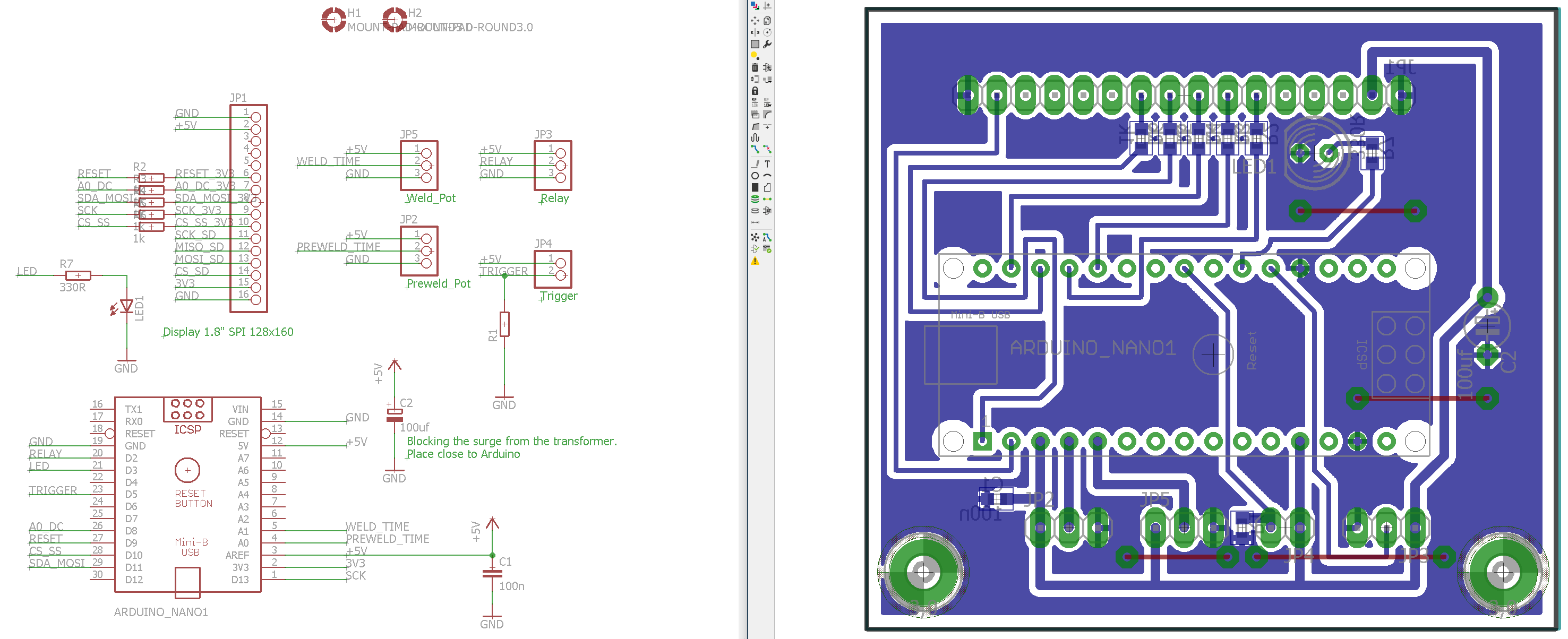
Certainly not a pretty board but it took me less than 2h to design it and 45 minutes to mill it on my PCB mill. Talk about rapid prototyping! I just wanted to get this over with because I was running out of vacation days.
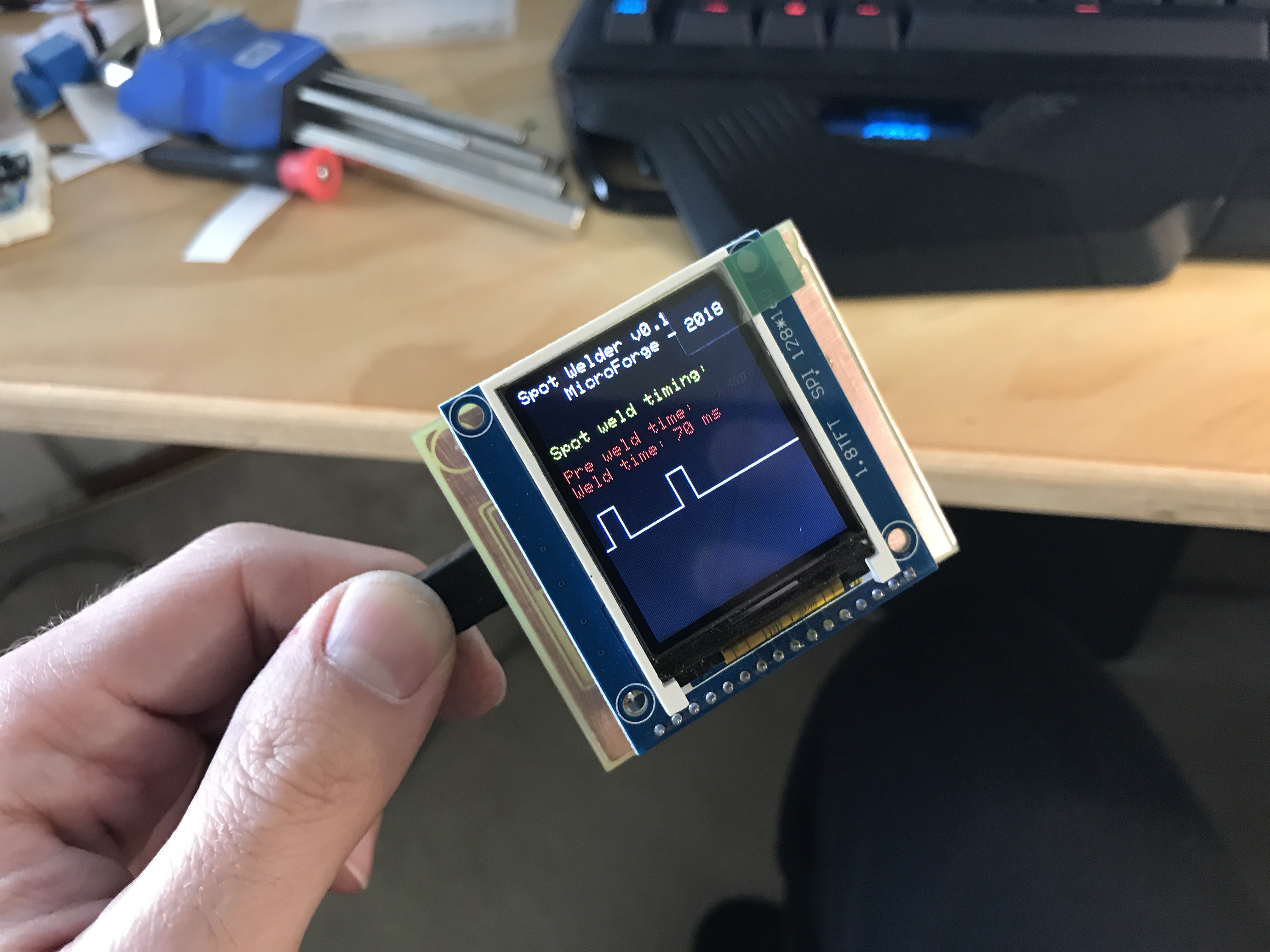
I put the board together and tested the design and I extremely happy when it powered up and worked right away.
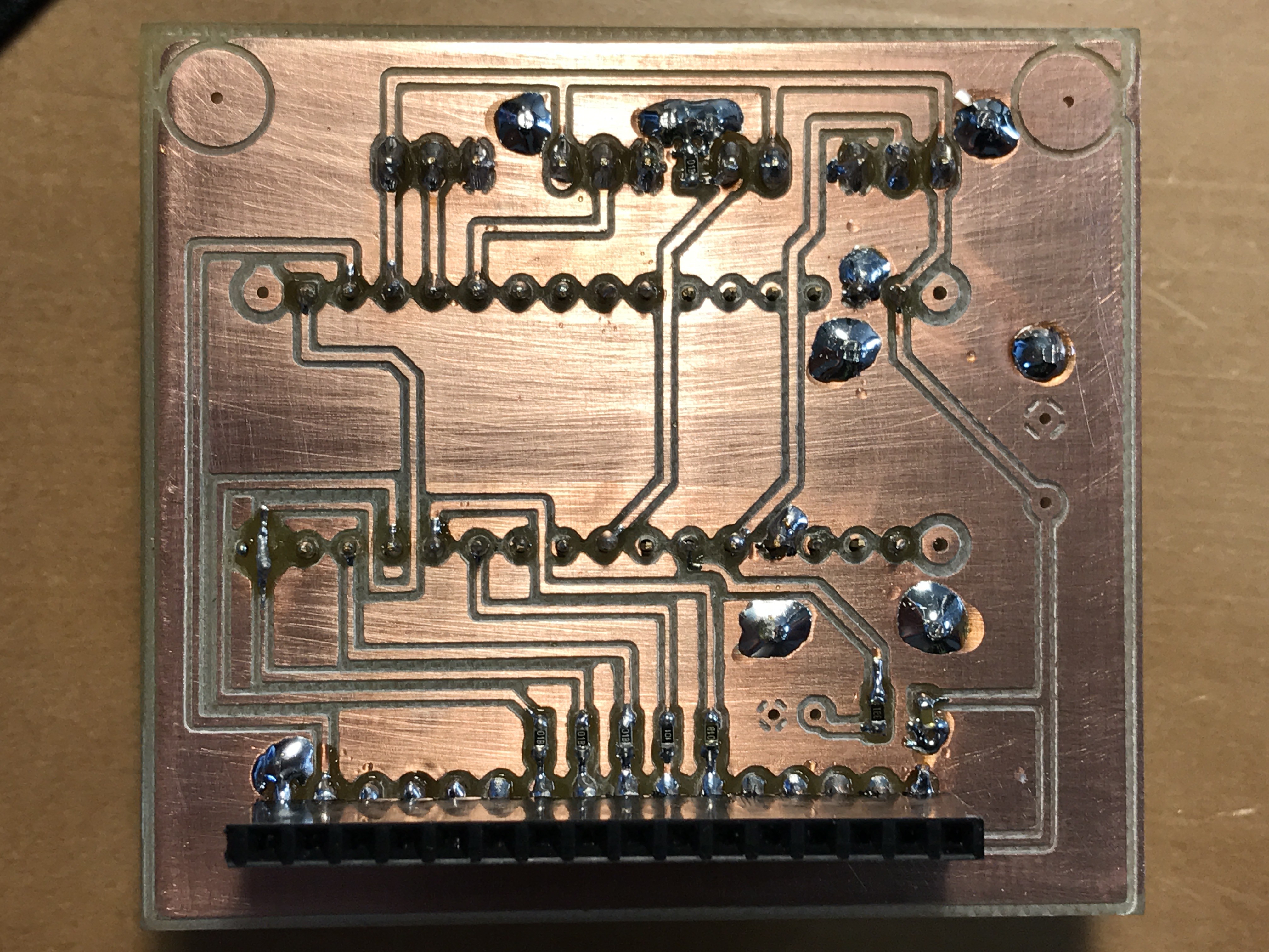
I love my PCB mill and I'm very happy with the results even though I need to make my restrings for vias and pads significantly larger from now on. It was also a mistake to drill the holes smaller than 0.8mm. Unfortunately, Eagle is still a bit dumb and gives very inconsistent results when making restrings larger in the design rules and then using copper filling around the traces and pads. Apparently, you can make restrings larger but the clearance around the pads won't automatically grow. As a result you will manually adjust the spacing around the traces and vias/pads but that will cause a lot longer milling times and also doesn't work with ground (GND) vias/pads for some awkward reason.
Discussions
Become a Hackaday.io Member
Create an account to leave a comment. Already have an account? Log In.