Close
0%
0%

R'lieh - Aquarium/ closed ecosystem management

An automated and connected aquarium management system

Public Chat
Similar projects worth following
R'lieh stands for "Remote Location Intelligent Ecosystem Handler", not to be confused with the sunken city of R'lyeh. It is a connected platform for automated management of a closed ecosystem, such as an aquarium, a terrarium, or a pond.
The main parameters that has to be handled by the system are the light and the temperature.
The system monitors the water temperature and tries to adapt it needed. The lights must also be turned on and off as programmed by the user.

If possible, i would like to monitor as many parameters as possible, such as pH, GH, KH, conductivity, nitrates, dissolved oxygen, CO2, etc... However, sensors for those parameters are a bit expensive, so i am still looking for other sensors.

Later on, i plan to add a system to automate water changes, with a peristaltic pump.
I also want to make an automated feeding system.
By automating everything, we can optimize the resources consumption of the system, having it drawing only what is required

Aquariums and terrariums can be seen as closed ecosystems. The problem is that they don't work as is. One can create a really closed ecosystem, but with very few animals, and specific species. Let's focus again on normal aquariums. In those, people want to have many colorful animals. The problem is that the more animals you have, the more pollution you get. In aquariums, fishes, shrimps, etc, produce wastes (the technical term is "poop", but not only) after consuming food (more on this topic in this post : https://hackaday.io/project/2929-rlieh-aquarium-closed-ecosystem-management/log/9806-water-qualitity-sensors).

The problem is that this pollution is toxic to most animals. It is really dangerous, as it can kill animals, whose corpses will produce more toxins, and kill even more animals.

Another problem is that fishes will produce carbon dioxide, and need oxygen to breathe. All in all, it is up to the aquarium's owner to ensure that the water is suitable for the animals.

One solution to improve water quality is to have real plants, since they consume animal wastes and carbon dioxin. With enough plants, the impact of animal pollution can be greatly reduced. Plants require mostly lights, and a few nutrients, some of which they can obtain from animal wastes.

Keep in mind that i'm being a bit schematic here in order to keep things simple, but this is the general idea.

So what is the problem here? With a good set of lights and enough plants, we should have no problems right?

Well, things are not often that simple. Indeed, have too few lights, and brown algae will colonize your tank, and the "good" plants will die. Too much light and you'll get green algae. Too many wastes, and you'll have another kind of algae. Even with the right amount of light, you have to turn it on and off, otherwise, the tank's inhabitants will end up having problems (most fishes can't close their eyes).

All in all, the first problem is that you have to control the lighting to have the correct intensity and the correct illumination. Most of the time, the problem is that aquarium don't have strong enough lights (or bad quality lights), so in order to solve this problem, there is no miracle solution. We'll use powerful lights. However the more powerful the lights, the more power they drain, given a chosen technology. Furthermore, powerful lights will produce heat, that can be detrimental to the aquarium (we'll discuss the problem of temperature later).

With more powerful lights, we waste more power, so we have to ensure that the lights are on only as long as it is required.

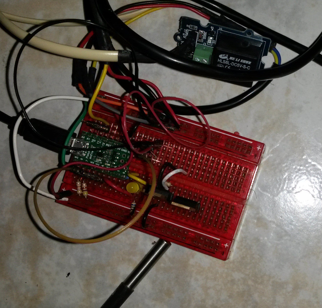
For this purpose, this project includes a system to handle the lights automatically. Indeed, manual control means that you can either forget to turn on the lights, causing some problems to the plants, or forget to turn it off, and have algae growth AND wasted power.

So the first function of Rlieh is to manage lights. It has to be able to turn it on and off, set a time for turning it on, and off (or a time to turn it on and a duration), and ideally it should allow us to have it fading it on and off, to replicate the sun rise and set (this is less stressful for the inhabitants). However, one can want to look at something in the tank for maintenance, and we have to be able to turn the lights on for that. The system should thus be able to override the current light state, with an auto-off after some time to prevent the user from forgetting to turn it off.

This post is already quite long, so i'll stop here, and discuss cooling in another post later. I'll also make a more synthetic post to summarize all these aspects for those that don't want to read those long blobs of text :)

  • 1 × Raspberry Pi arm microcomputer
  • 1 × ATmega328p Microprocessors, Microcontrollers, DSPs / ARM, RISC-Based Microcontrollers
  • 2 × DS18B20 Sensors / Temperature, Thermal
  • 3 × 80mm PC fans ventilation/cooling
  • 1 × TIP120 Discrete Semiconductors / Power Transistors and MOSFETs

View all 8 components

  • The assembled board

    Audrey Robinel11/25/2016 at 13:39 0 comments

    In the previous post, we saw the PCBs. I have now assembled a few ones, and tested it.

    There were a few errors on the board, and a new revision is on the way from the fabhouse.

    However, those boards are still functional, and here is how it looks once the assembly is done :

    You can see the two mosfets on the left, controlling two output channels (lights by default, but can be used for fans, or whatever DC systems that can be controlled with PWM).

    The 2 pins lock connetors are tied to the outputs of the mosfets (4 connectors per mosfet), and the 3 pins lock connectors are tied to the arduino GPIOs. On the top row, there are 4 connectors -3pins- that are tied to the same GPIO, D2, with a pull-up 4.7k resistor. Those are meant for use with temp probes (DS18B20 or similar). D3 and D5 controls the mosfets, and all other PWM GPIOs are broken out on other 3 pins connectors. On the bottom, 2 analog pins are also broken out on the same connector with the same pinout.

    The Extension1 connector breaks out the other digital pins, as well ass ground and +5V.

    On the top right is the I2C RTC module, and below are 4 connectors for I2C (GND, VCC, SDA and SCL). One of those connectors is used for the LCD, others can be used for whatever.

    The second 6 pins connector (Extension2) breaks out the 4 remaining analog pins as well as +5V and ground.

    The 3 pin connector labelled 5Vin is connected to the +5V of the arduino and can be used to provide it 5V or to gather 5V for something else.

    At last there are 2 other connectors visible : a red 2 pins connector and a locking 2-pin one beside it. The locking one is for DC in, and it is the current switched by the mosfets, so it can be quite high.

    If using a jumper on the red connector, however, the tension used must be limited to about 12V, because it will also be fed to the arduino linear regulator. It can bear a little bit more depending on the load on 5V, but the official doc specifies to put in 7-12V there.

    So you can drive 12V AND power the arduino with it, or provide it external 5V and drive higher tensions through the mosfets.

    This has the same pinout as the mosfet outputs, so that if plugging the wrong cable in the wrong place, no damage is dealt.

    There is a last connector that can't be seen on this picture, behind the arduino, again a 2 pins jumper connector.

    With the jumper on, it connects a capacitor to the reset pin, in order to prevent auto-reset on serial connection. If removed, the reset works as intended, and the arduino can thus be programmed normally.

  • PCB

    Audrey Robinel11/01/2016 at 13:37 0 comments

    Rlieh now has a real PCB instead of protoboards :)

    It holds all the required components and breaks a lot of GPIOs :

    This board also has extensions connectors for unused connectors, as well as jumpers to enable or disable power trough the arduino regulator, or disable the auto reset on serial.

    The PCB is about 5*7cm, with M3 holes in each corners. This is the same footprint and fix holes as the 5*7 perfboard, so that it can be used as a drop-in replacement for the protoboards, and use the same cases :)

    On the following picture you can see the back of the board (middle one) :

    I'm pretty satisfied with it, and it was greatly manufactured!

    In the next post, we will show an assembled board and describe it a bit.

  • Front panel interface

    Audrey Robinel04/05/2016 at 03:49 0 comments

    I made a box for the LCD and buttons, printed out of PLA. Here is the result on my print bed :

    on the next picture, there is a Raspi zero for size comparison :

    The LCD mounts on from the back and is secured with 3mm short screws. The buttons are inserted from the front and secured with a nut.

    Once the LCD is connected (using I2C, so only 4 cables : power, ground, sda and scl), the system can be powered on : ,

    here it prints the state of the first light on the first line (On/OFF).

    On the second line, it prints what it is doing (turning on or turning off), since turning on or off is not instantaneous, but progressive, and takes some time. Thus, i wanted to know if it was in the process of turning on or off. With long rise and fall times, it can help.

    The third line shows air temperature, and water temperature (eau, in french).

    Then, the last line prints the time and date (french format)

    For now, only the top button does anything : it forces the light to turn on or off (progressively, but faster than normal fade in/out times). There is an override variable in the code, and after some time, the normal light state is restored.

    If it is off, and i press the button, it will quickly fade in, and stay on for 5 minutes (that's my setting). Then it fades out. If you override when on, it will do the same, although i'll change it to have it stay off untill next normal lights fading in. Indeed, if i turn it off while it's on, it's probably because i want to go to sleep early, so, it should stay off longer than 5 minutes.

    The temperature is provided by two DS18B20 probes, and the time by a small RTC module.

  • Base arduino module

    Audrey Robinel01/23/2016 at 19:17 0 comments

    This project has not progressed for quite some time, so i decided to work a little bit on it. Planned features are still planned, but as i said in a previous post, i'm making the arduino base module independent. That way, if there is a Raspberry Pi connected, advanced functionalities are available, but if not, it will still work and do it's job.

    So i've made a simple module that is able to read temperature from two DS18B20 probes, one for air temperature, another for water temperature, and controls the lights of the aquarium. Using a TIP120, it powers 12V led strips, controlling it with PWM. There is an RTC module to keep track of time, and an I2C LCD to print informations. So as of now this it what it does:

    • Read and print air temperature on LCD;
    • read and print water temperature;
    • print time and date;
    • turn lights on automatically:
      • on time can be set;
      • lights fade in duration can be set;
    • turn lights off automatically
      • off time can be set;
      • lights fade out duration can be se
    • up to 8 temperature probes are physically supported on the current design;
    • two independent outputs are planned, each with PWM.

    This is the core of the functionalities for automating the system. However, manual control is still possible, with a button that can override the automatic settings for a configurable duration. As of now, if i press the button while the lights are off, it fades in for 5 minutes, at a faster rate than normal (but still not a brutal off-on transition). After that duration it returns to the normal state (off).

    If it was the time for the lights to be on, it fades off quickly for the same duration. In the future, i plan to have a different duration for off override. Indeed, if it's on and i want it off, it's probably because i want to go to sleep without an aquarium light in my room. Hence a longer override, until the next natural "morning" (ie the next time when lights should turn on).

    In case of power loss, it runs the normal course of the program, turning on or off depending on the time (it doesn't remember the override commands issued, that are stored in ram, and thus lost on power loss or reset).

    In all cases, messages are print on the LCD, and you know if the lights are completely off, fading out, fading in, or completely on. The LCD backlight also turns of with the lights. In the next revision, i'll add a few buttons that will be used as an interface to set things such as fade duration, on and off time, override duration, etc... I'll keep the quick override button, but also add a small menu controllable with a few other buttons.

    Everything in the code is made in non-blocking, so that i didn't have to use interrupts.

    Here are the next steps :

    1. add more buttons;
    2. add the control menu;
    3. make the LCD backlight turn off AFTER the lights shutdown (LCD backlight is on or off, as it's an I2C one);
    4. have a different value for the off override, or be able to override until next phase;
    5. have the system print more than two temperature probes, and be able to assign a label to each with the interface rather than in the code;
    6. reintegrate the previously coded temperature controls (turn a fan or a device on and off depending on temperature);
    7. reintegrate the serial communications code;
    8. make a case for 3D printing or laser cutting for it.

    I'll post the schematics and the code soon (of this version, so it doesn't mean in months :) )

  • Communications

    Audrey Robinel09/23/2015 at 17:57 0 comments

    I previously used serial communications trough USB to exchange data with a master node. Now, i'm reconsidering this. Indeed, i'll try to give more autonomy to the arduino node, with an RTC to keep track of time. The idea being that if i want to use juste the Arduino module to control the system, i can.

    I'm keeping the xml communication protocol available over USB. However, rather than plugging this node to a master node (raspberry pi), i think that i'll make it able to handle itself, as well as beeing able to recieve orders from other nodes.

    Then, i'll leave the option of controlling it either from USB, with a direct connection, or trough the network, via an ESP8266.

    I will thereby have a small and cheap node, capable of autonomous functionning, with the possibility to manage it via a physical interface (buttons, potentiometers, etc), or via the network, from a web browser.

    I'm leaning towards this architecture because of some work i'm doing with another project, Dhomochevsky, oriented towards domotics, home automation, and smart home, and Milapli, a network of sensors for a meteo station.

    Considering that the aquarium controller has many sensors, i want to be able to use those for the two other projects as well, rather than just log the data for this application. All of this will be optionnal, i'll be looking for a way to create some kind of web service to make informations available.

    Anyway, now i'm working on ESP8266, and i'll probably make a new design for this aquarium controller when i get the hang of those wifi modules.

  • Code

    Audrey Robinel05/26/2015 at 03:53 0 comments

    A quick post to provide a link to the latest available code :

    https://github.com/sarinkhan/Rlieh/tree/master/raspberryPi

    This link contains the code that runs on the raspberry pi. However, this is mostly just python code, and the essential aquarium functions use nothing specific to the pi. The only specific files that are written for the raspi are the ones that prints stuff onto a 20*4 lcd screen. the rest is compatible with any linux box.

    The www folder contains php files to provide a simple way to control it over the network (be warned, it's extremely basic code, and it will really need to be fleshed out in order to obtain a nice interface, as of now it's just a way to call the python scripts through an URL via a browser).

    https://github.com/sarinkhan/Rlieh/tree/master/arduino

    The arduino folder contains rlieh3.ino, the code that has to be uploaded onto a whateverduino (arduino uno, leonardo, mega, etc... basically anything with a Atmega 328p, a 32u4 or anything bigger).

    Once hooked with sensors and stuff, it will be able to control various organs. I'll soon put instructions for hooking up. As of now, some instructions can be found on the old fritzing sketches, and pins must be figured by reading the top of the code (everything is specified there, with comments), or even changed in the code.

  • Arduino serial reset

    Audrey Robinel05/22/2015 at 17:50 0 comments

    I encountered something that caused me trouble today. I set up the system for real world use, but each time i was sending a command to the arduino, i was having the relays turning of prior to everything.

    Here is a quick test code :

    #!/usr/bin/python
    from time import sleep
    import serial
    
    print("opening serial")
    
    ser = serial.Serial("/dev/ttyUSB0", 9600)
    waitTime1=0.2
    
    print ("waiting")
    sleep(waitTime1)
    print("sending cmd")
    ser.write("R1Off")
    sleep(waitTime1)
    ser.write("R2Off")
    sleep(waitTime1)
    ser.close()
    sleep(waitTime1)
    This one turns off the relays, and there is another file for turning them on.

    The problem was that on connect, all relays shut down. I figured out that when a serial connection is established to the arduino, it resets. Hence the shutdown of the relays. in order to handle that, the solution is to put a capacitor between the vcc line and the reset pin :

    http://forum.arduino.cc/index.php/topic,28723.0.html

    I don't yet know the minimal value that can be used, but it works with 220µF.

    Thanks to this, i was able to have the commands working without resetting anything. I thus don't have to have a daemon connected to the arduino handling requests from other programs.

  • Saving variables in EEPROM

    Audrey Robinel05/15/2015 at 20:00 0 comments

    The cooling system is set to turn on at 24.5°C and off at 24°C. However i made it so that it is possible to change this value. By sending the command "setLowTemp1:X", the low temperature will be set to X, and there is a command to set the high temperature. However, without further modifications, the values would be lost after a power loss. In order to prevent that, i decided to store the values in the Atmega328p. A way to save values in the chip is to write them in the EEPROM.

    For those unfamiliar with this concept, EEPROM stands for Electrically Erasable Programmable Read-Only Memory. I invite you to read more on the subject of EEPROM on this wikipedia link.

    On the ATMega chips, there is some EEPROM memory, and on the ATMega328p, there is 1024 Bytes of EEPROM (http://playground.arduino.cc/Code/EEPROM-Flash).

    By default, in order to access the EEPROM, one would use the EEPROM.h library described on Arduino.cc.

    However, it only supports reading and writing int values from 0 to 255. Since i had to store floats, and didn't want to fiddle with this, i used the EEPROMex.h library. It is meant to be used in the same way as the basic library (code written for EEPROM.h works with this lib), but extends it by adding read and write functions for many types, including floats.

    I thus added the following section in my code :

    if(cmd  =="setLowTemp1")
        {
          if(param0f!=-1.0)
          {
            lowTemp1=param0f;
            EEPROM.updateFloat(lowTemp1Address,lowTemp1);
            printCmdResultXML(0, true, lowTemp1Tag+" set");
          }
          else
          {
            printCmdResultXML(1, true, missingArgumentString+":"+lowTemp1Tag);
          }
        }
        else if(cmd  =="getLowTemp1")
        {
          Serial.print(openTag1+lowTemp1Tag+closingTag);
          Serial.print(lowTemp1);
          Serial.println(openTag2+lowTemp1Tag+closingTag);
        }
    His section handles the commands related to the low temperature (the second only shows it, but the first one is used to store it in the EEPROM. I used the update function rather than write so that if it is unchanged, it won't actually write it, preserving the memory. Indeed, it has 100 000 writes per cell, so it's better not to overuse it in vain.

    In the setup function of the ATMega328p, i use this to retrieve the values :

      lowTemp1=EEPROM.readFloat(lowTemp1Address); 
      highTemp1=EEPROM.readFloat(highTemp1Address);
    With this, i can now save user specified values for some settings.

    I will probably add the possibility of storing the fading time int the EEPROM as well.

  • Code optimization

    Audrey Robinel05/14/2015 at 12:43 0 comments

    I had issues with the code. it turns out that i was using too much ram on the *duino..

    Indeed, each string is counted as global variable, and space is sparse on an Atmega328p : you have 2048 Bytes of RAM. The device is meant to answer to simple commands (such as getWaterTemp), and returns XML like strings. Those strings among other things was taking too much space. Furthermore, writing Serial.println("blablabla") two times takes twice as many ram, the system doesn't free the ram after the first call.

    I hence had to clean the code. In order to do that, i declared strings containing all the text that was repeated more than once, or that is likely to be so in the future. I also compacted messages, reducing all unnecessarily long error messages.

    All those changes reduced the RAM taken from more than 2048 Bytes to 1356 Bytes.

    With this change, all bugs have disappeared, and now all functions are properly working. One good side effect is that messages are coherent : when something is on, the status will be reported as "ON" everywhere, rather than "On", "on", or "ON" in various locations.

    As of now, the system controls two relays (on, off, and returning status of the relay), two TIP120 transistors (on, off, set to PWM level, and status), one of which is used to control the lighting described in a previous post. The second one will be used to cool the water (as of now, fans blowing towards the surface, but later on maybe a pelletier chilling the water). Two DS18B20 temperature probes are also accessible (one for air, another for water).

    The cooling is set to turn on when a threshold temperature is reached, and shuts down when another lower temperature is obtained. I used two values (24 for low, 24.5 for high) so that the cooling doesn't turns on and off all the time around the target value.

    Multiple functions are also available for lighting, but i already covered that in a previous post. It is also possible to set a number of variables trough the serial commands, such as low and high temperature thresholds, lights fade time, etc.

    Every function described here can be activated by serial, but the state of each subsystem can be obtained in the same way at any time.

    The code has been written entirely without delays, so the device never "hangs" waiting for something. This makes the board quite responsive.

    In order to improve this aspect, i did set the Serial.timeout to 100ms, wich is enough at 9600 bauds fo all commands. Thus, when a command is sent, it is executed in 100ms, and a response is sent after this delay. By default, the timeout is set to 1000ms.

  • Pre-version of the USB control board

    Audrey Robinel04/15/2015 at 06:12 0 comments

    I made great progress on the USB control board. Here is a picture of a prototype:

    I am using an AStar 32U4 micro, from Pololu as a USB interface. Indeed, i planed to use a bare ATMega328p, but this was cheap (aprox 5$ during black friday), while being compact and retaining most of the functionalities of a regular arduino. Since it was so cheap, i decided to use it rather than a circuit based on a Atmega328p with wires for serial communications going to the serial port of the Raspberry pi. It enables the user to use this device with whatever computer, provided that it has drivers for USB-serial.

    I chose this model because it was cheap, and i had a few laying around, but any arduino will do.

    Anyway, this little board has GPIOs connected to two relays, two (perhaps 3, later on) TIP120 transistors, 3 DS18B20 temperature sensors (one regular, two waterproof). The relays are intended to control mains current. The first TIP120 is there to control strips of LED through PWM. A second TIP120 transistor controls fans used to cool down the water. The third TIP120, if used, will control a TEC unit, used to further chill down the water.

    The temperature sensors are there to monitor the water temperature, and the air temperature. I have two tanks, so at first i'll monitor both tanks temperatures, but later on, the second water temperature sensor will be used to monitor the water chiller temperature.

    As of now, this unit will control both tanks, but later on i want to have one unit per tank.

    All of those sensors and effectors are controlled through serial. As of now, i can send various commands to turn on and off the lighting or even fading it in and out. The relays are simply switched on or off, and their state can be monitored over the serial port (you send "getRelay1Status", and get "on" or "off" in return). The extra transistors will be controlled via PWM, and thus the duty cycle will be set through serial. Again, the status of each transistor can be probed. At last, each temperature sensor can be probed via serial (you send getWaterTemp1, and get the first waterproof sensor's reading).

    I have mostly written the code on the Astar, then i'll write programs to send serial commands to the device.

    I also plan to add in the protocol a way to set some settings, such as the temperature at which the fans will start, etc.

    I am considering adding an RTC clock, so that the device can handle turning the lights on and off automatically, without a master controller. If so, the device could be plugged into a computer to set it up once, then run autonomously. I however want to log data, and have a web interface to review and control the system, so i'll connect it to a raspberry pi anyway. However, i could instead use an ESP8266 for wifi connection.

    For now, no physical interface is visible on the device, because i want the buttons, LCD, etc, to be connected to the Raspberry pi (or computer connected to the device).

    See you next!

View all 19 project logs

Enjoy this project?

Share

Discussions

Andreas Klostermann wrote 03/21/2018 at 12:37 point

I have a couple of suggestions:

- If you try to automate water changes, it will certainly be faster and cheaper to use a cheap 12V submersible pump. There are also youtube videos on how to realize automatic water changes.

- Rather than use expensive sensors which wear out after a relatively short amount of time (a year or so), use a peristaltic pump and some servos to pump a small amount of water into small test tubes at preplanned intervals. These need not be very frequent, because these values don't change very often anyway. Then you can test them manually with the normal methods. It's more work, but a lot cheaper. Even for a bigger setup with multiple aquarium systems, it would be cheaper to draw samples automatically and then have them analyzed by sensors manually.

- A nice sensor to have, though, is a turbidity sensor. And maybe something to measure light absorption. Both of which may tell you things about over feeding and algae problems.

- It's relatively simple to make a conductivity sensor. The conductivity of the water relates to PH and electolytes. It can't easily be converted to Ph values, but it would be a way to have a higher time resolution on changes in PH. 

  Are you sure? yes | no

hohm.michel wrote 10/15/2017 at 16:51 point

BONJOUR

j'aimerai savoir comment sont brancher les boutons de commande sur l'arduino

d'avance merci

  Are you sure? yes | no

Audrey Robinel wrote 02/05/2015 at 14:02 point

I'm looking forward to see the evolution of your project, but rather than for electronic probes, with chemicals. Perphaps with one system per chemical (to keep chemicals from mixing). However, the question of how to reliably pour a few drops of a solution within 5ml of water remains!

  Are you sure? yes | no

Audrey Robinel wrote 02/05/2015 at 16:46 point

I am aware of such systems. However, i have yet to experience it to ensure that it can be used for really small volumes (drops). Indeed, the tubing also contains some volume, so it has to be tweaked!

Other than that, there is the problematic of isolating the liquid from air, i.e. some kind of valve.

As for the srynge pump, a more precise solution is to use a screw to push the mobile part of the srynge rather than just push a rod (in the same fashion of a 3D printer Z axis), and a stepper!

But sure, i have to try all those stuff, and compare the result to manual measurements :)

All in all, all those bits together could provide a good solution for this problematic.

  Are you sure? yes | no

James Newton wrote 02/03/2015 at 20:38 point

When you get to the sensors for nitrates, etc... you might take a look at my project:

https://hackaday.io/project/4197-reagent-robot

  Are you sure? yes | no

Similar Projects

Does this project spark your interest?

Become a member to follow this project and never miss any updates