 Audrey Robinel
There were a few errors on the board, and a new revision is on the way from the fabhouse.
However, those boards are still functional, and here is how it looks once the assembly is done :
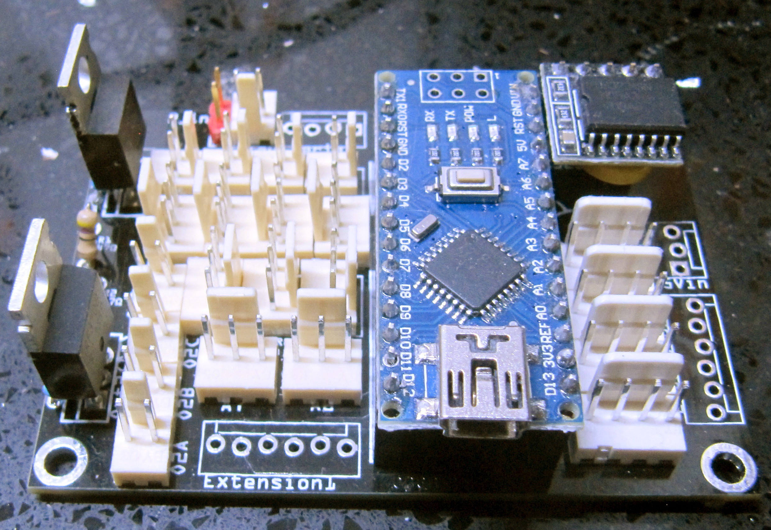
You can see the two mosfets on the left, controlling two output channels (lights by default, but can be used for fans, or whatever DC systems that can be controlled with PWM).
The 2 pins lock connetors are tied to the outputs of the mosfets (4 connectors per mosfet), and the 3 pins lock connectors are tied to the arduino GPIOs. On the top row, there are 4 connectors -3pins- that are tied to the same GPIO, D2, with a pull-up 4.7k resistor. Those are meant for use with temp probes (DS18B20 or similar). D3 and D5 controls the mosfets, and all other PWM GPIOs are broken out on other 3 pins connectors. On the bottom, 2 analog pins are also broken out on the same connector with the same pinout.
The Extension1 connector breaks out the other digital pins, as well ass ground and +5V.
On the top right is the I2C RTC module, and below are 4 connectors for I2C (GND, VCC, SDA and SCL). One of those connectors is used for the LCD, others can be used for whatever.
The second 6 pins connector (Extension2) breaks out the 4 remaining analog pins as well as +5V and ground.
The 3 pin connector labelled 5Vin is connected to the +5V of the arduino and can be used to provide it 5V or to gather 5V for something else.
At last there are 2 other connectors visible : a red 2 pins connector and a locking 2-pin one beside it. The locking one is for DC in, and it is the current switched by the mosfets, so it can be quite high.
If using a jumper on the red connector, however, the tension used must be limited to about 12V, because it will also be fed to the arduino linear regulator. It can bear a little bit more depending on the load on 5V, but the official doc specifies to put in 7-12V there.
So you can drive 12V AND power the arduino with it, or provide it external 5V and drive higher tensions through the mosfets.
This has the same pinout as the mosfet outputs, so that if plugging the wrong cable in the wrong place, no damage is dealt.
There is a last connector that can't be seen on this picture, behind the arduino, again a 2 pins jumper connector.
With the jumper on, it connects a capacitor to the reset pin, in order to prevent auto-reset on serial connection. If removed, the reset works as intended, and the arduino can thus be programmed normally.
Discussions
Become a Hackaday.io Member
Create an account to leave a comment. Already have an account? Log In.