 Audrey Robinel
I chose for this project to use a Raspberry Pi for the connected part, storing data, etc. Hovever, i also use a microcontroller (Atmega328p, because i have some, but a Attiny will also do!). I could have used the RaspberryPi GPIO to control the lights and other stuff, and indeed, i did.
For my grand mother tank, that is what i did. The problem is that aquariums are lit by neon tubes (most often, in this case it was), that generates quite a lot of EMI. The problem was that the pi was able to start the neon, but would stop reacting to the buttons afterwards. I had to reboot the Pi to make it work again. I tried to shield the pi with an aluminium plate, but it didn't work. I thus made a quick breadboard arduino whith a atmega328p at 8Mhz (no crystal).
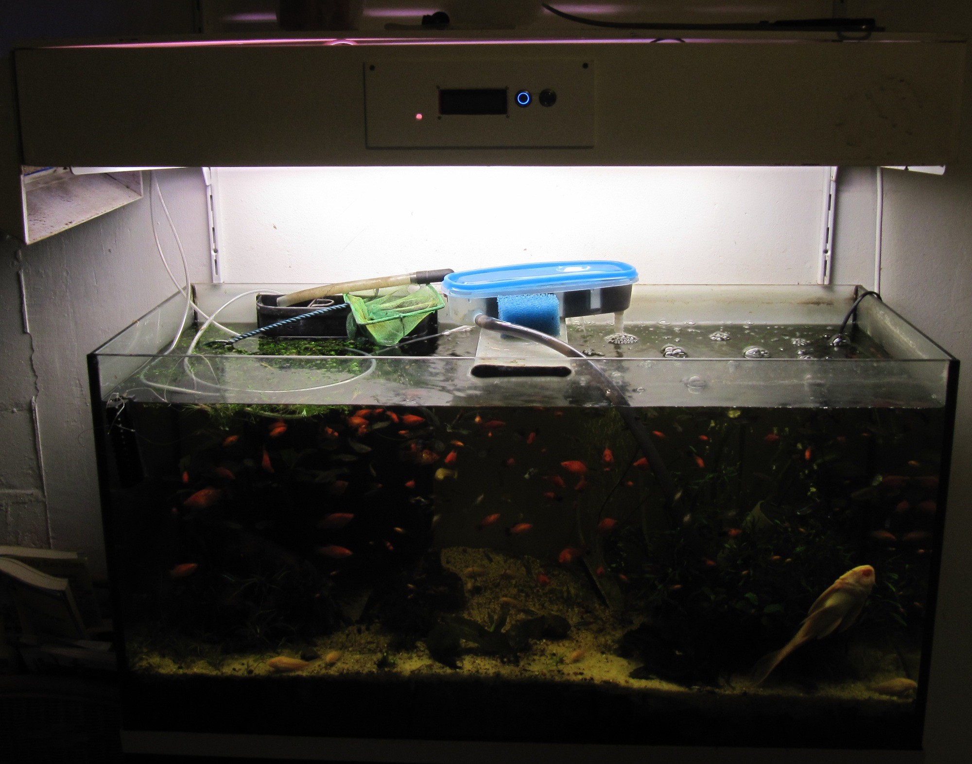
On the above picture, the neon box (i made it from plywood) with the button for the lights. The Raspi inside the box doesn't work, whereas the Atmega does. The LCD is off since i removed the Raspi untill i find a solution. For this installation, the fans are always on. The tupperware here is a filter that i made, as the original filter was not efficient enough, and not easy to clean (read more about my filter prototype here).
Even when the breadboard was on top of the neon tube, it kept working. It still does, after a few months. What i learnt from this is that the microcontroller is much more solid and resilient than the pi. It oriented my design choices, and now the architecture is to have a µC controlling the lights and all essential systems. The µC is connected in some way to the Raspberry Pi, that can issue commands to it. That way, even if the pi fails, i can manually control the system through a simple backup interface.
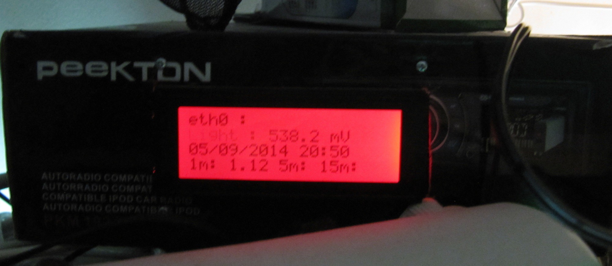
The Raspberry pi is connected to my wifi network, and can thus keep track of time using NTP (i know i could have added a RTC. But i have spare wifi keys, and no RTC clocks...). It then turns on the lights at an user defined time, for an user defined duration (it sends a "on" signal to the atmega, that turns the relay on. After some time, it sends a "off" signal). The Raspberry Pi also has a 4*20 LCD screen for all kind of user feedback (water temp, clock, IP, etc).
For now, the atmega also handles temperature management , by controlling a 12v transistor to switch 3 80mm PC fans. It senses water temperature using a DS18B20, and turns the fan on when the water temp exceeds 24.5°C, and off when it goes below 24°C. I coded it this way in order to keep the system from constantly turning the fans on and off. Furthermore, a little variation of temperature reproduces natural conditions, and is some times needed for some species to breed.
The air temp in this room is around 26 to 29°C during the day, often lower at night. For now, it is hard-coded, later on it will be set by the user. I will discuss the cooling of an aquarium later in another post, as i am testing pelletier cooling, and i will compare the performance with what i can obtain by simple evaporative cooling (fan blowing towards the water surface).
| The arduino part, with the fans | The lights box, the bulbs beeing protected by a plexyglass plate. The fans shroud is also visible. |
 | 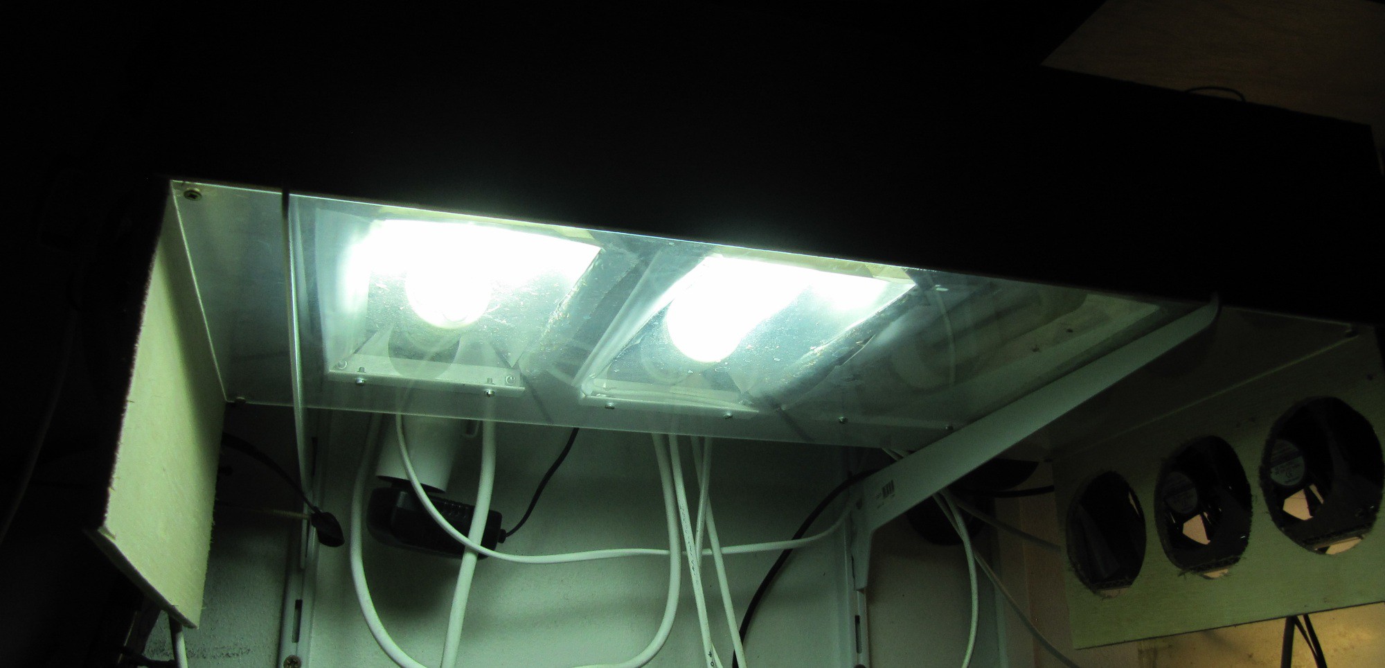 |
As of now, other parameters are not yet monitored, i may add a flowmeter to monitor the filter output, and i will be looking forward to montior other physical and chemical parameters of the water.
See you in the next post :)
Discussions
Become a Hackaday.io Member
Create an account to leave a comment. Already have an account? Log In.