 Audrey Robinel
Hi! Today, i committed a github release containing new files for the project. There is a new fritzing file, along with png, jpg, svg and pdf version of the schematics.
Those file describe the fully functionnal prototype (it has to be tested, updates may come soon). This prototype aims to reproduce and/or enhance the functions of my current system (also based on arduino and raspi but less elaborated).
I also posted an anoted picture :
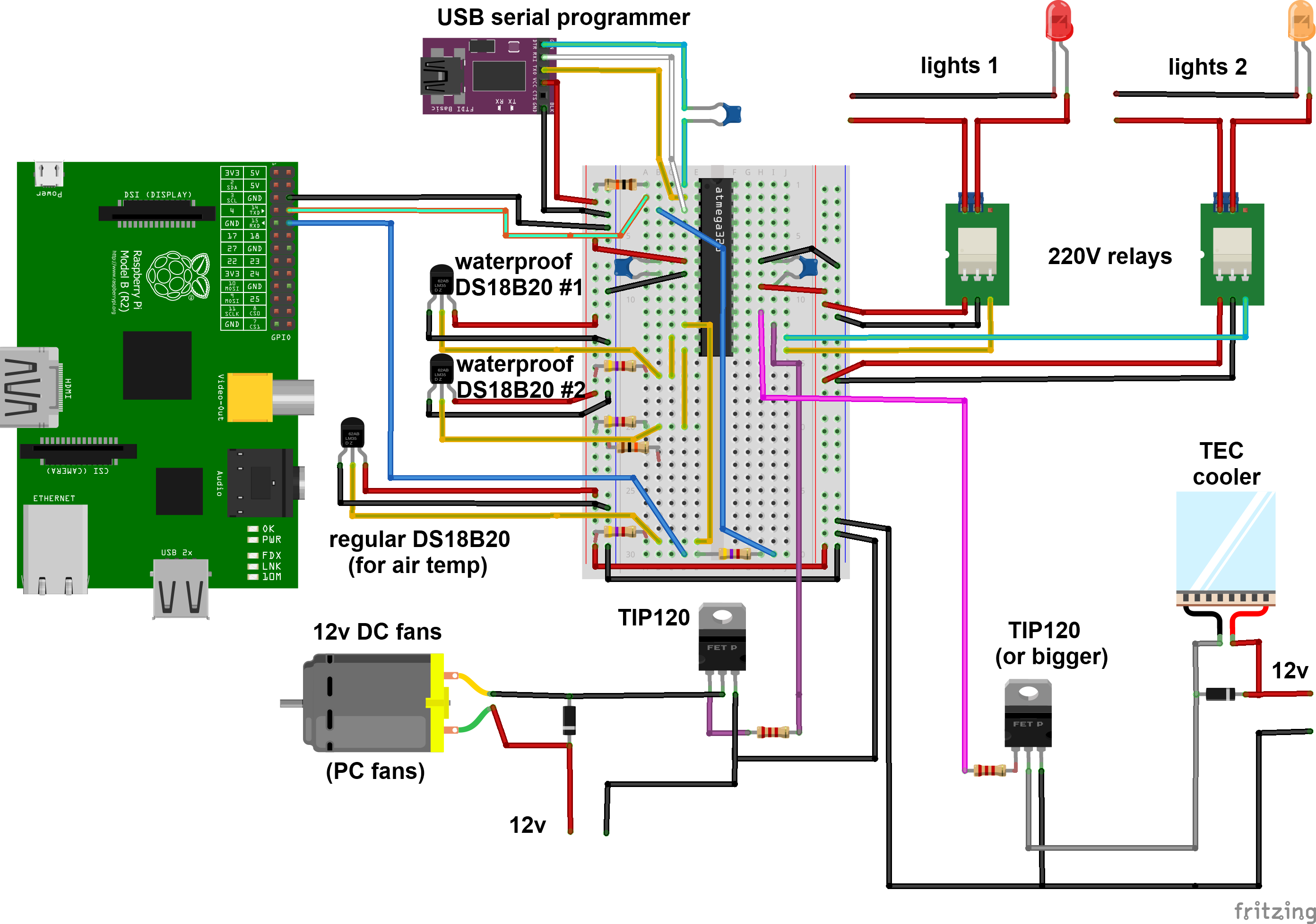
So i have two relays for controlling 220V lights (works with 110V of course). As mentioned in a previous post, those are smal relay boards, with protection diode and leds to check if it is working or not. This explains why i just connect those to a gpio without further protection. I have two relays for my two tanks, but more could be easily added, and used to turn the lights on progressively (one tube, then another, etc) or to control more systems. In the end i plan to use LED, so this will change. However, this part of the circuit may be used for whatever mains current device we need to turn on and off.
For DC current devices i use TIP120 transistors. In my case, one for controlling 12v 80mm PC fans (3 in parallel). Those fans are blowing towards the surface, and reduces water temperature of 2 to 4°C.
I included another TIP120 for controlling a TEC that i plan to use for cooling the water further if needed. The TIP120 is rated for 5A continuous use, my TEC is supposed to drain up to 4 amps at 12V, so i'll try it.
At last, i have DS18B20 probes for temperature monitoring. I will include two waterproof ones, in order to monitor both tanks water temperatures, and a regular one to monitor air temperature. This third probe is not really needed, but since i have it, and have spare GPIO, i will include it. For now, the fan is turned on and off depending on water temperature. Later on, it may be PWM controlled, and i may use the air temperature readings to anticipate water temperature rises (if air temp reaches 28°C whereas water is at 24°C as an example, i can monitor how long it takes to warm up the water to a certain temperature, and then decide when to start cooling it to prevent it from warming up then beeing cooled). I could also use it to either use the TEC to cool the water if air temp is too high, or use the fans if it is low enough to save power.
Anyway, it's always nice to have data about the environement of the tanks.
I have a partially done prototype for this circuit, i will complete it and test it. Once i am satisfied with the design i may solder it on stripboard. I also have "perma - protoboards" with a breadboard layout and a raspi ribbon connector, i may try to make an expansion board for the raspi directly.
See you next, with the arduino sketches :)
Discussions
Become a Hackaday.io Member
Create an account to leave a comment. Already have an account? Log In.