 Audrey Robinel
If you only want to monitor water temperature and control two sets of lights, here is a simple circuit i made for testing serial communications:
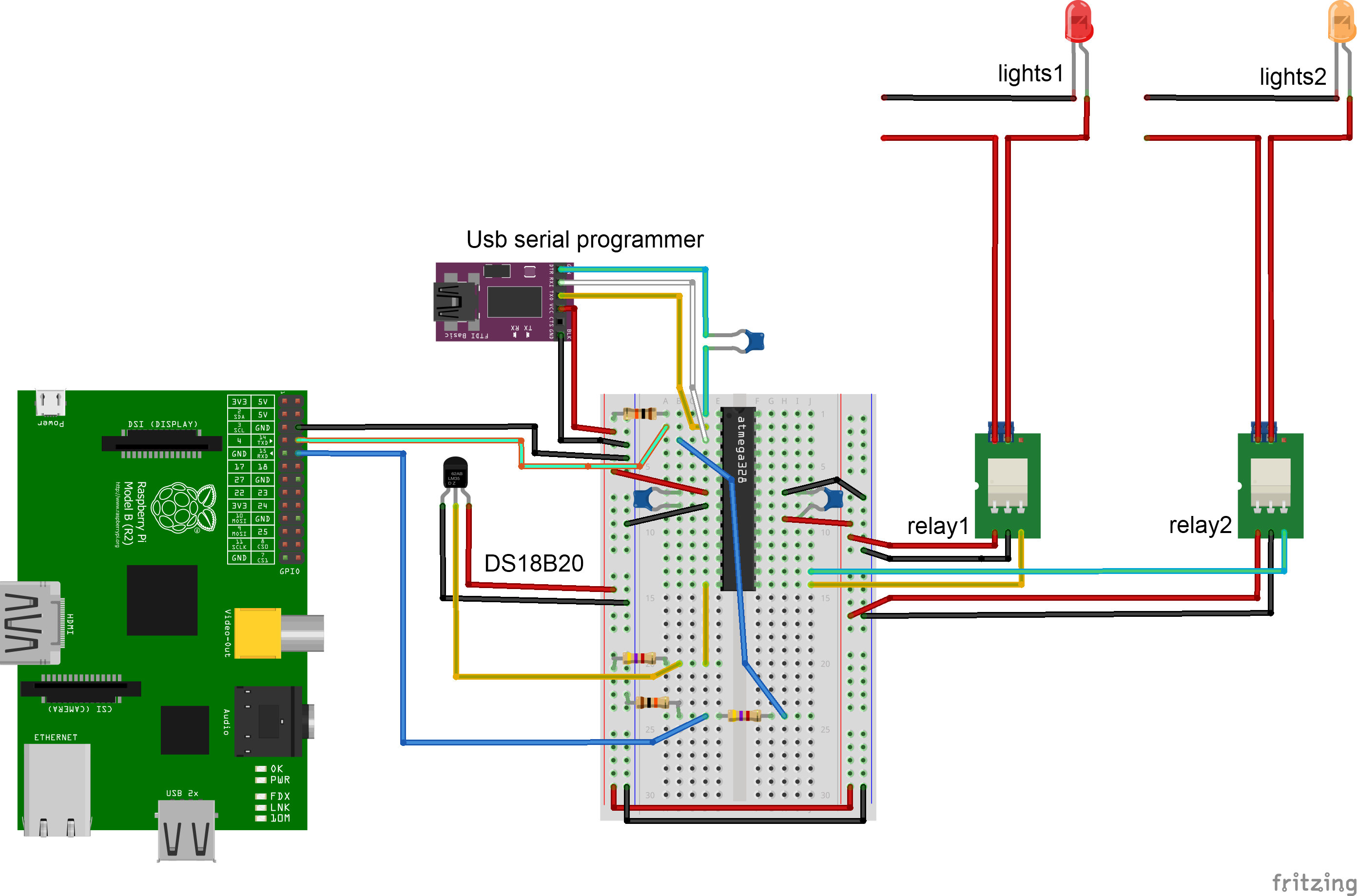
I made a breadboard arduino based on an ATMega328p, with the bootlader set for using the internal 8Mhz oscillator. I program it with a serial-usb board, than can stay plugged or not in operation (this way you can read the arduino serial messages both on the Raspberry Pi AND on the Arduino soft, or remove the serial programmer when needed elsewhere).
Be sure to unplug the serial cables before trying to program the arduino, otherwise it will fail, with a message about no sync.
The DS18B20 is connected with a pull up resistor, and the relays are connected to GPIO. If you use bare relays, you have to include a flyback diode and maybe a few more stuff to protect the GPIO from current spikes from the coil. I am using small relay boards, with everything on it. Each relay in my case has a VCC input (5V, red wire), ground (black wire) and a signal wire. There are two screw terminals, for the mains wire. If the signal input is high, the current is allowed to pass trough the relay, otherwise it is not allowed to.
The fritzing file for this circuit can be downloaded in this commit on the github, with the PNG, SVG and PDF version.
In the next version, i will add the transistor used to control the cooling, thus regaining the functionnality of the previous prototype. So stay tuned for the next update, soon!
Discussions
Become a Hackaday.io Member
Create an account to leave a comment. Already have an account? Log In.