0%
0%
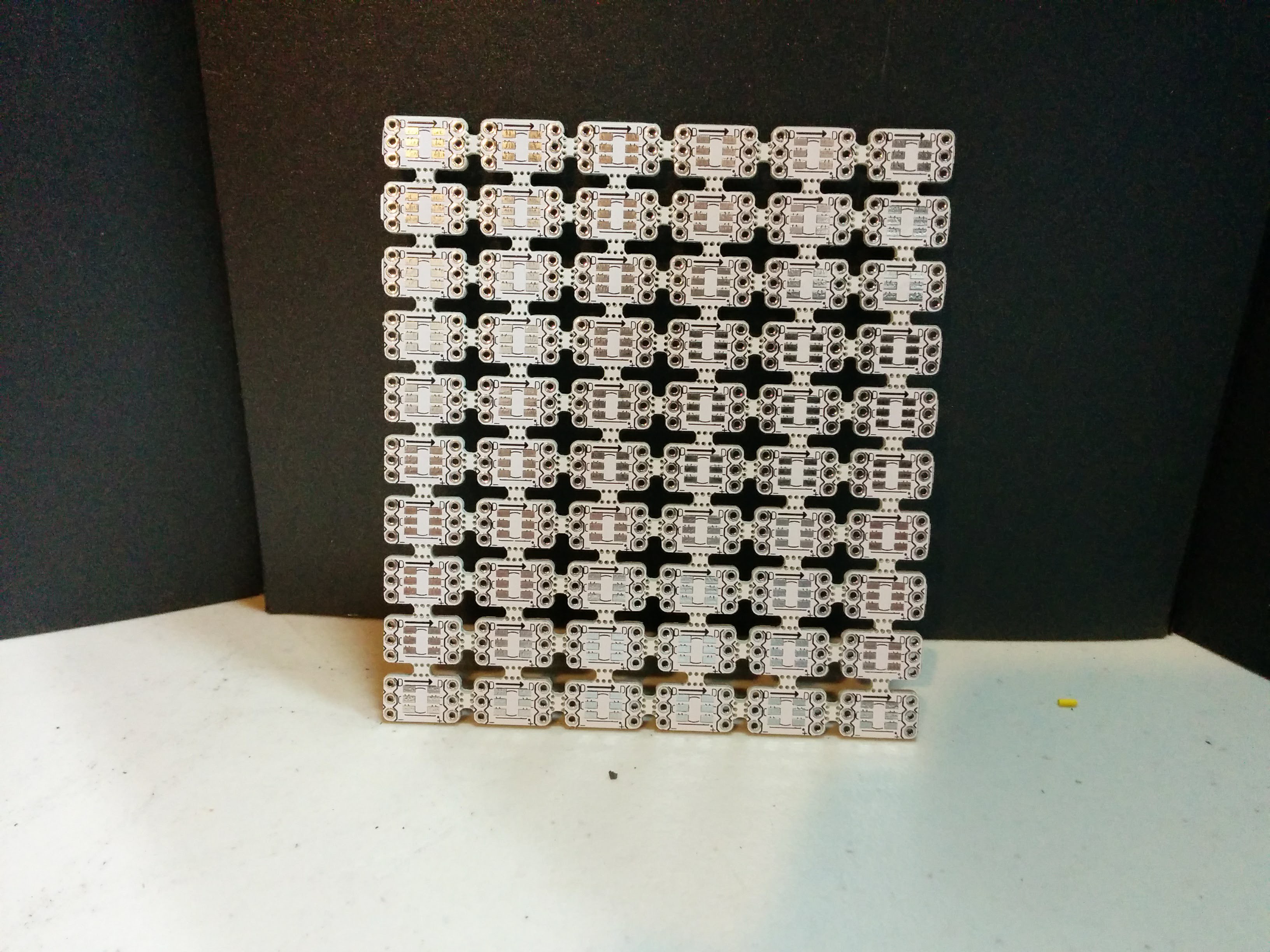
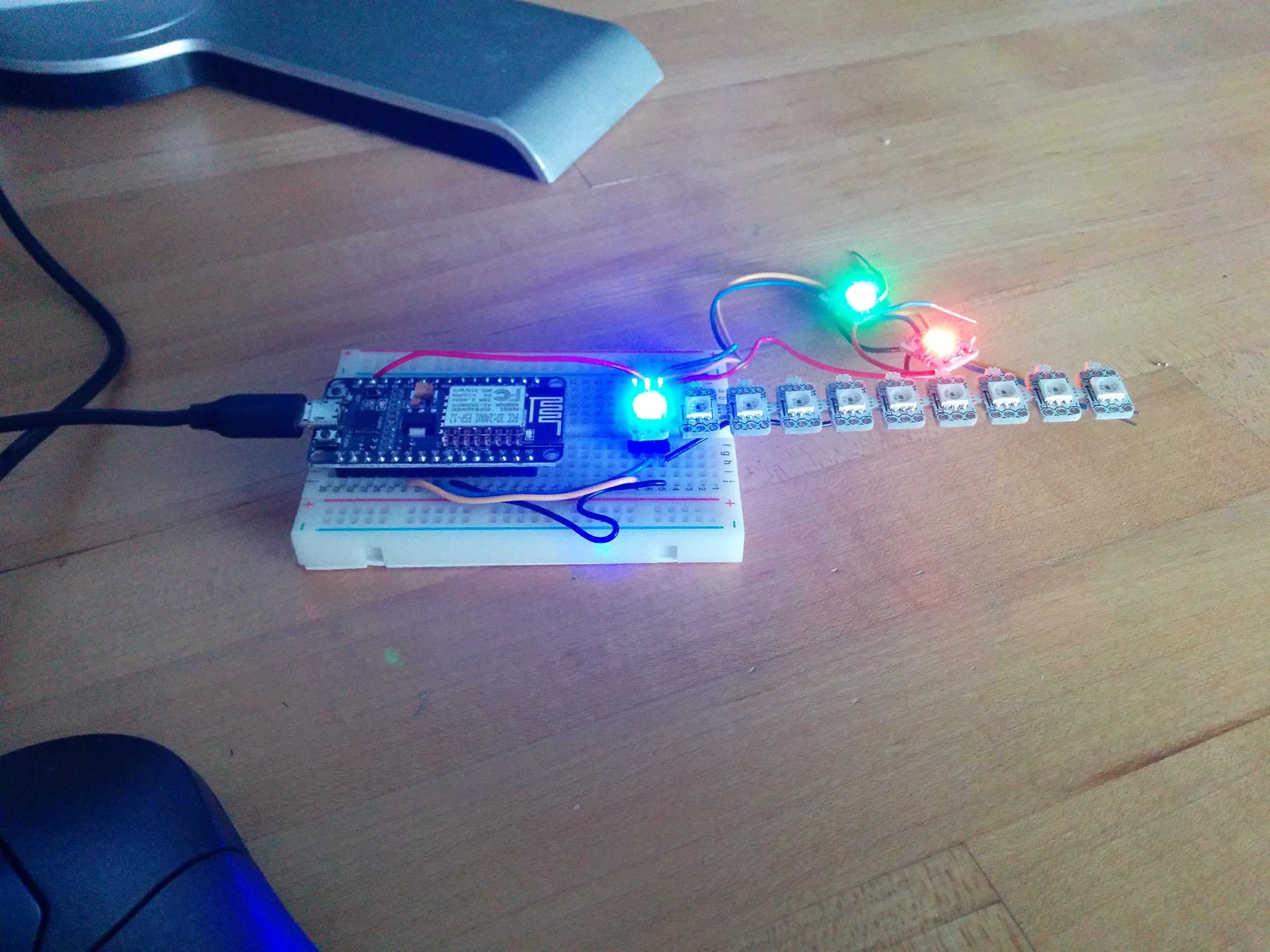
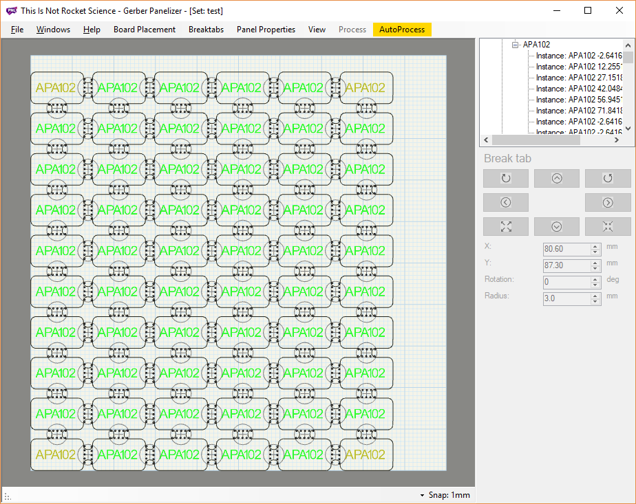
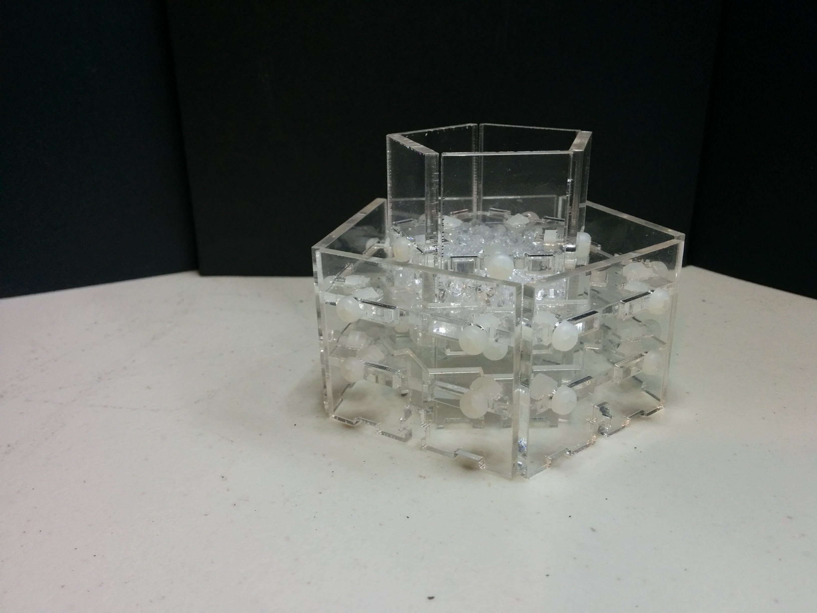
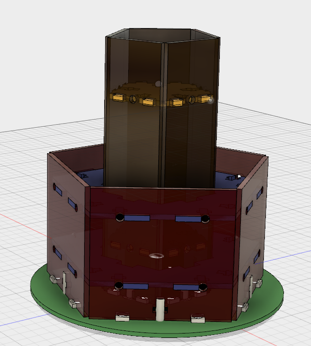
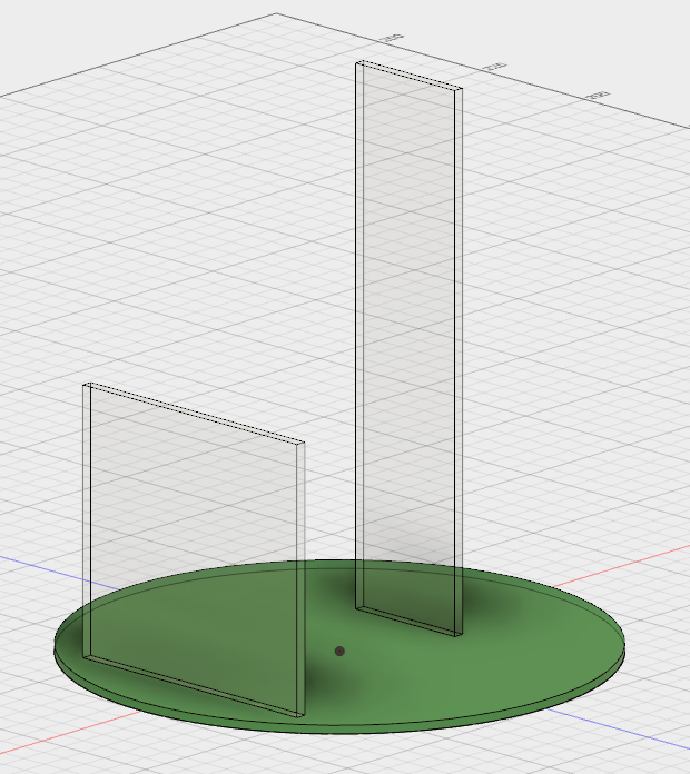
A Hacker's Wedding Centerpiece(s)
Im getting married :D. I've been put incharge of making the coolest* centerpieces ever!
(*coolest acording to me)
 bveina
Become a Hackaday.io member
Already have an account? Log in.
Just one more thing
To make the experience fit your profile, pick a username and tell us what interests you.
Pick an awesome username
hackaday.io/
Your profile's URL: hackaday.io/username. Max 25 alphanumeric characters.
Pick a few interests
Projects that share your interests
People that share your interests


 engunneer
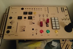
 Matthew Peverill
 RRichmond
 charliex
Thats pretty devious, i like it, time permitting...