 Nikodem Bartnik
When I got my first Arduino as a present for Easter in 2014 I decided to make a POV display, because it was a very effective and I only had few parts like LEDs and resistors. I had no idea on how to make this thing, I even didn't know how POV display works. So I started searching for some explanation on the internet, I made a prototype on the cardboard with breadboard and tape. After a lot of tries I got it working. Then I added a motor to make it spin and it started to work. That's the story of my first Arduino project, that's how I started my journey with Arduino. Since that I build a lot of projects: EggBot, Drone, Voice controlled lamp, FollowBot, Snake robot and a lot of normal robots. So choosing POV display as a first project was great idea. But it's time to make a second version of this project. It's time to make it better, simpler and smaller. So that more beginners can start with this project.
To make it I designed a custom PCB in KiCAD. PCBs were made by JLCPCB.COM, huge thanks to them for supporting this project. Because I already now how POV displays work, I decided to complicate this project a little bit to make it more challenging. The first thing to make it harder was using a KiCAD instead of Eagle, I have never used KiCAD so that's my first design. I also use as many SMD components as it was possible, to reduce it's size and price but also to learn soldering small SMD components, because I haven't a lot of experience with SMD soldering.
I made a mistake with PCB design. I used ADC6 and ADC7 pins to control LEDs but it turns out that those two pins can't be used as an output, they are only for analog input. To fix that I added two jumpers between pins PD3 and PD4 and LEDs number 7 and 8. Except this small mistake (or maybe not so small) this project is really good. I am happy that I manage to design a board in KiCAD, produce it, solder and create a code for it. So if you want to make something like this follow the instructions below. If you like it, don't forget to hit that like button, any questions leave in the comments.
Happy making!
 Amitabh Shrivastava
 DIY GUY Chris
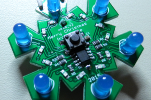
 HybridAir
 Jefferson Bueno