Close
0%
0%

Bat Sonar

Bat like sonar sensor that can track multiple targets and estimate angle of arrival using chirps and cross correlation in near real time.

Similar projects worth following
Existing air sonar modules are pretty low tech so only track one target, don't handle background noise very well, or targets too close to the sensor. I wanted to see if it was possible to improve the design to provide more sensor information for applications in multirotors and robots, while still keeping it reasonably small and low cost (ie no expensive FPGA or arrays of many high cost transducers).

In my research I found that bats can echolocate obstacles in 3D space, and at close range can detect the location and velocity of 1mm prey. Biological sonar employ many different strategies which include modifying the output chirp based on task, leveraging two input sensors, using ear shape to change input response based on vertical source, and others.

Using ultrasound in air has some inherent limitations with range and accuracy, relative to other mediums like salt water. But it still makes sense to see how far one could get.

Video showing the bat sonar in action

This video shows the sensor in action.  The left graph shows the identified targets.  The size of the circles indicates the strength, and the location on the graph is their measured location.  The graph on the right shows the cross correlation signal vs distance.  The first step is pressing a switch on the board to calibrate and baseline the sensor.  Then the video shows the sensor identifying various targets.

How it works:

Chirp Generation

Using a counter and interrupt, the MCU generates a sequence of time periods that vary in period.  At each time period, the ADC is used to output a voltage, alternating between (1.65-amplitude) and (1.65+amplitude) with 1.65 volt as the midpoint (1/2 of supply).  The maximum frequency, minimum frequency, number of pulses, and amplitide can therefore be controlled in software.  Note that this produces a square wave chirp.  Typical ranges used are 60kHz to 30kHz and from 32 cycles to 256 cycles duration (where 1 cycle counts as a positive and negative pulse in the pulse train).
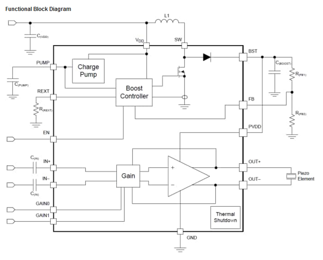
Chirp generated is period modulated using a timer interrupt and DAC.

Output Stage

The output of the ADC is amplified by two op amps in a push pull fashion, resulting in a gain factor of 12, resulting in a maximum swing of 39.6v p-p output at the ultrasonic transmitter.  The amplifier output drives the ultrasonic transducer in series with an inductor and resistor.  These provide compensation to flatten the response of the transducer, which by itself is tuned at 40KHz.  See this paper for details.

Output Stage
Output stage uses push-pull op amps and 40 volt supply

Ultrasonic Echos

The chirp passes through the air and reflects off of one or more targets.  It also gets transmitted directly to the micrphones, as well as bounces off the surface the sensor rig is on and produces false echos.  We will get to how we deal with those later.

Microphones detect false echos as well as true targets


MEMS Microphones

The MEMS microphones are within 2.8mm of each other, which is less than 1/2 the wavelength of the signals used, which results in unambiguous phase detection.  Each microphone is sampled at 4MHz to capture signals with high time resolution. 

MEMS Microphones
Distance between the microphones is less than 1/2 wavelength.

MCU Microphone Input

The MCU has an I2S peripheral with 2 channels which is used to sample the microphones at 4MHz.  A fifo buffer of 5 32-bit words is used on each channel with an interrupt on buffer full to write to RAM.   No DMA was used since I could not get it to work and my napkin calcs showed it would not save a lot of processor time.  For each microphone, a maximum buffer of 10,000 32-bit words are used to collect the PDM data.  A 10,000 word buffer holds 80msec of data, which translates to 1060 inches of sound travel, a range of 530 inches.  The size of the buffer is software controlled so that shorter range windows(and corresponding faster processing times) can be configured.

void I2S_Int(void)
//I2S interrupt routine called when buffer is full
//Loop unrolled for speed
{
    if(memsbuffer_i < (sample_size-4))  //buffer of 5
    {
        memsbuffer0[memsbuffer_i]=I2S0_RDR0;
        memsbuffer1[memsbuffer_i]=I2S0_RDR1;
        memsbuffer_i = memsbuffer_i +1;

        memsbuffer0[memsbuffer_i]=I2S0_RDR0;
        memsbuffer1[memsbuffer_i]=I2S0_RDR1;
        memsbuffer_i...
Read more »

Full Sonar v1 opt corrected external clock.sch

Eagle Schematic for a dedicated board containing the complete system.

sch - 447.78 kB - 08/19/2018 at 12:19

Download

Full Sonar v1 opt BOM.txt

BOM for the dedicated board with the complete system.

plain - 8.55 kB - 08/19/2018 at 12:19

Download

Full Sonar v1 opt corrected external clock.brd

Eagle BRD file for a dedicated board containing the complete system.

brd - 208.26 kB - 08/19/2018 at 12:18

Download

Interconnection Diagram.png

Diagram showing how to connect the prototype boards

Portable Network Graphics (PNG) - 781.04 kB - 01/28/2018 at 19:57

Preview
Download

power proto routed.sch

Eagle schematic for the output stage

sch - 337.04 kB - 01/07/2018 at 22:33

Download

View all 11 files

  • 1 × FRDM-K64F ARM Cortex M4 board from NXP (formerly Freescale)
  • 2 × SPH0641LU4H-1 Knowles ultrasonic MEMS microphone
  • 1 × UT-1240K-TT-R PUIAudio ultrasonic transmitter 30vrms
  • 1 × MIC2297-42YML-TR Power Management ICs / Switching Regulators and Controllers
  • 1 × MC34072AMTTBG 3-44 V DUAL OPAMP VIO

  • Dedicated board

    Filip Mulier08/19/2018 at 12:16 0 comments

    Since March I have been working on a dedicated board to contain the whole system.  Here is the link to the OSH park board

    https://oshpark.com/shared_projects/JiEvGsBk

    Caution - the output stage produces 80 volt peak to peak which is dangerous, but also within specs for the sonar transducer.

    Improvements

    • This board has improved power supply decoupling and less ripple.
    • It has an input for 5v power to supply the current for the 40volt internal step up supply.
    • Microphone holes in the board are better and solder pattern better match specs
    • Microphone holes are 2.7mm apart
    • High accuracy clock
    • Complete self-contained board.

    Issues

    • Minor amount of noise on the transducer output - sounds like noise from the MCU.   Likely routing issue- capacitive coupled analog input close to digital output.  Does not seem to affect performance.

  • Another option for the output stage

    Filip Mulier02/04/2018 at 11:42 0 comments

    TI makes a combined boost converter and amplifier for piezo applications.  Its called the DRV2700.  Using this would reduce the parts count a bit, including reducing the resistors needed in the current opamp circuit.  Will need to consider for future prototype.

View all 2 project logs

Enjoy this project?

Share

Discussions

Similar Projects

Does this project spark your interest?

Become a member to follow this project and never miss any updates