 Filip Mulier
Video showing the bat sonar in action
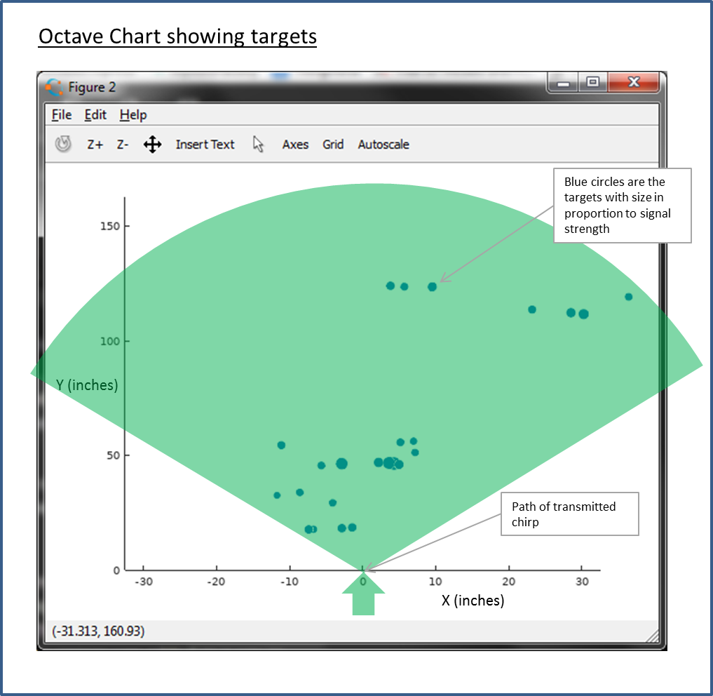
This video shows the sensor in action. The left graph shows the identified targets. The size of the circles indicates the strength, and the location on the graph is their measured location. The graph on the right shows the cross correlation signal vs distance. The first step is pressing a switch on the board to calibrate and baseline the sensor. Then the video shows the sensor identifying various targets.
How it works:
Chirp Generation
Using a counter and interrupt, the MCU generates a sequence of time periods that vary in period. At each time period, the ADC is used to output a voltage, alternating between (1.65-amplitude) and (1.65+amplitude) with 1.65 volt as the midpoint (1/2 of supply). The maximum frequency, minimum frequency, number of pulses, and amplitide can therefore be controlled in software. Note that this produces a square wave chirp. Typical ranges used are 60kHz to 30kHz and from 32 cycles to 256 cycles duration (where 1 cycle counts as a positive and negative pulse in the pulse train).

Output Stage
The output of the ADC is amplified by two op amps in a push pull fashion, resulting in a gain factor of 12, resulting in a maximum swing of 39.6v p-p output at the ultrasonic transmitter. The amplifier output drives the ultrasonic transducer in series with an inductor and resistor. These provide compensation to flatten the response of the transducer, which by itself is tuned at 40KHz. See this paper for details.

Ultrasonic Echos
The chirp passes through the air and reflects off of one or more targets. It also gets transmitted directly to the micrphones, as well as bounces off the surface the sensor rig is on and produces false echos. We will get to how we deal with those later.

MEMS Microphones
The MEMS microphones are within 2.8mm of each other, which is less than 1/2 the wavelength of the signals used, which results in unambiguous phase detection. Each microphone is sampled at 4MHz to capture signals with high time resolution.

MCU Microphone Input
The MCU has an I2S peripheral with 2 channels which is used to sample the microphones at 4MHz. A fifo buffer of 5 32-bit words is used on each channel with an interrupt on buffer full to write to RAM. No DMA was used since I could not get it to work and my napkin calcs showed it would not save a lot of processor time. For each microphone, a maximum buffer of 10,000 32-bit words are used to collect the PDM data. A 10,000 word buffer holds 80msec of data, which translates to 1060 inches of sound travel, a range of 530 inches. The size of the buffer is software controlled so that shorter range windows(and corresponding faster processing times) can be configured.
void I2S_Int(void)
//I2S interrupt routine called when buffer is full
//Loop unrolled for speed
{
    if(memsbuffer_i < (sample_size-4))  //buffer of 5
    {
        memsbuffer0[memsbuffer_i]=I2S0_RDR0;
        memsbuffer1[memsbuffer_i]=I2S0_RDR1;
        memsbuffer_i = memsbuffer_i +1;

        memsbuffer0[memsbuffer_i]=I2S0_RDR0;
        memsbuffer1[memsbuffer_i]=I2S0_RDR1;
        memsbuffer_i = memsbuffer_i +1;

        memsbuffer0[memsbuffer_i]=I2S0_RDR0;
        memsbuffer1[memsbuffer_i]=I2S0_RDR1;
        memsbuffer_i = memsbuffer_i +1;

        memsbuffer0[memsbuffer_i]=I2S0_RDR0;
        memsbuffer1[memsbuffer_i]=I2S0_RDR1;
        memsbuffer_i = memsbuffer_i +1;

        memsbuffer0[memsbuffer_i]=I2S0_RDR0;
        memsbuffer1[memsbuffer_i]=I2S0_RDR1;
        memsbuffer_i = memsbuffer_i +1;

        I2S0_RCSR = I2S0_RCSR | I2S_RCSR_FEF_MASK;

    }
    else
    {
        //disable, reset fifos, turn off interrupts, but keeps bit clock on
        I2S0_RCSR =  I2S_RCSR_FR_MASK| I2S_RCSR_WSF_MASK| I2S_RCSR_SEF_MASK| I2S_RCSR_FEF_MASK| I2S_RCSR_FWF_MASK| I2S_RCSR_BCE_MASK;
    }

}
Matched Filtering using Cross Correlation
The next step is matched filtering on one of the microphone channels to identify the targets. Only one microphone is used at this stage, to identify the targets. I found an approach in this paper that works natively on PDM signals. This approach takes advantage of how the cross correlation problem simplifies when its matching a simple square wave chirp with a 1-bit PDM stream. In this case its a sum of delays with terms reflecting the signal level changes in the chirp and delays reflecting the length of each pulse in the chirp. This reduces the computational complexity significantly. Note that its done in the time domain, not using the FFT as is typical with higher resolution digital samples. The Cortex M4 has SIMD (Single Instruction Multiple Data) and DSP instructions that I carefully tuned to maximize computation speed.

The code snippet below was an early version of the code to calculate the cross correlation at a single time point. It comes out of a code generator I made in excel, that reflects the work in the paper above. The chirp waveform is hard coded in the delays for each term, so its easier to see how it works. The SWARx2 function calculates the popcount x 2, and bit_lookup returns groups of 32 bits at arbitrary boundaries within the microphone buffer (i.e. not necessarily on byte boundaries). It does not take advantage of the SIMD or DSP instructions. Later versions of the code do, and also change the order of computation to speed things up, but they are difficult to understand without first understanding this.
corr_calc = corr_last-SWAR(bit_lookup(memsbuffer,timestamp+0));  //first positive slope pulse 1
corr_calc += -SWARx2(bit_lookup(memsbuffer,timestamp+32));  //first sample after negative edge pulse 1
corr_calc += +SWARx2(bit_lookup(memsbuffer,timestamp+65));  //first sample after positive edge pulse 2
corr_calc += -SWARx2(bit_lookup(memsbuffer,timestamp+100));  //first sample after negative edge pulse 2
corr_calc += +SWARx2(bit_lookup(memsbuffer,timestamp+135));  //first sample after positive edge pulse 3
corr_calc += -SWARx2(bit_lookup(memsbuffer,timestamp+172));  //first sample after negative edge pulse 3
corr_calc += +SWARx2(bit_lookup(memsbuffer,timestamp+209));  //first sample after positive edge pulse 4
corr_calc += -SWARx2(bit_lookup(memsbuffer,timestamp+248));  //first sample after negative edge pulse 4
corr_calc += +SWARx2(bit_lookup(memsbuffer,timestamp+288));  //first sample after positive edge pulse 5
corr_calc += -SWARx2(bit_lookup(memsbuffer,timestamp+328));  //first sample after negative edge pulse 5
corr_calc += +SWARx2(bit_lookup(memsbuffer,timestamp+370));  //first sample after positive edge pulse 6
corr_calc += -SWARx2(bit_lookup(memsbuffer,timestamp+413));  //first sample after negative edge pulse 6
corr_calc += +SWARx2(bit_lookup(memsbuffer,timestamp+457));  //first sample after positive edge pulse 7
corr_calc += -SWARx2(bit_lookup(memsbuffer,timestamp+502));  //first sample after negative edge pulse 7
corr_calc += +SWARx2(bit_lookup(memsbuffer,timestamp+548));  //first sample after positive edge pulse 8
corr_calc += -SWARx2(bit_lookup(memsbuffer,timestamp+596));  //first sample after negative edge pulse 8
corr_calc += +SWARx2(bit_lookup(memsbuffer,timestamp+644));  //first sample after positive edge pulse 9
corr_calc += -SWARx2(bit_lookup(memsbuffer,timestamp+693));  //first sample after negative edge pulse 9
corr_calc += +SWARx2(bit_lookup(memsbuffer,timestamp+744));  //first sample after positive edge pulse 10
corr_calc += -SWARx2(bit_lookup(memsbuffer,timestamp+795));  //first sample after negative edge pulse 10
corr_calc += +SWARx2(bit_lookup(memsbuffer,timestamp+848));  //first sample after positive edge pulse 11
corr_calc += -SWARx2(bit_lookup(memsbuffer,timestamp+901));  //first sample after negative edge pulse 11
corr_calc += +SWARx2(bit_lookup(memsbuffer,timestamp+956));  //first sample after positive edge pulse 12
corr_calc += -SWARx2(bit_lookup(memsbuffer,timestamp+1012));  //first sample after negative edge pulse 12
corr_calc += +SWARx2(bit_lookup(memsbuffer,timestamp+1068));  //first sample after positive edge pulse 13
corr_calc += -SWARx2(bit_lookup(memsbuffer,timestamp+1126));  //first sample after negative edge pulse 13
corr_calc += +SWARx2(bit_lookup(memsbuffer,timestamp+1185));  //first sample after positive edge pulse 14
corr_calc += -SWARx2(bit_lookup(memsbuffer,timestamp+1245));  //first sample after negative edge pulse 14
corr_calc += +SWARx2(bit_lookup(memsbuffer,timestamp+1306));  //first sample after positive edge pulse 15
corr_calc += -SWARx2(bit_lookup(memsbuffer,timestamp+1368));  //first sample after negative edge pulse 15
corr_calc += +SWARx2(bit_lookup(memsbuffer,timestamp+1432));  //first sample after positive edge pulse 16
corr_calc += -SWARx2(bit_lookup(memsbuffer,timestamp+1496));  //first sample after negative edge pulse 16
corr_calc += +SWARx2(bit_lookup(memsbuffer,timestamp+1561));  //first sample after positive edge pulse 17
corr_calc += -SWARx2(bit_lookup(memsbuffer,timestamp+1628));  //first sample after negative edge pulse 17
corr_calc += +SWARx2(bit_lookup(memsbuffer,timestamp+1695));  //first sample after positive edge pulse 18
corr_calc += -SWARx2(bit_lookup(memsbuffer,timestamp+1764));  //first sample after negative edge pulse 18
corr_calc += +SWARx2(bit_lookup(memsbuffer,timestamp+1833));  //first sample after positive edge pulse 19
corr_calc += -SWARx2(bit_lookup(memsbuffer,timestamp+1904));  //first sample after negative edge pulse 19
corr_calc += +SWARx2(bit_lookup(memsbuffer,timestamp+1976));  //first sample after positive edge pulse 20
corr_calc += -SWARx2(bit_lookup(memsbuffer,timestamp+2048));  //first sample after negative edge pulse 20
corr_calc += +SWARx2(bit_lookup(memsbuffer,timestamp+2122));  //first sample after positive edge pulse 21
corr_calc += -SWARx2(bit_lookup(memsbuffer,timestamp+2197));  //first sample after negative edge pulse 21
corr_calc += +SWARx2(bit_lookup(memsbuffer,timestamp+2273));  //first sample after positive edge pulse 22
corr_calc += -SWARx2(bit_lookup(memsbuffer,timestamp+2350));  //first sample after negative edge pulse 22
corr_calc += +SWARx2(bit_lookup(memsbuffer,timestamp+2428));  //first sample after positive edge pulse 23
corr_calc += -SWARx2(bit_lookup(memsbuffer,timestamp+2508));  //first sample after negative edge pulse 23
corr_calc += +SWARx2(bit_lookup(memsbuffer,timestamp+2588));  //first sample after positive edge pulse 24
corr_calc += -SWARx2(bit_lookup(memsbuffer,timestamp+2669));  //first sample after negative edge pulse 24
corr_calc += +SWARx2(bit_lookup(memsbuffer,timestamp+2752));  //first sample after positive edge pulse 25
corr_calc += -SWARx2(bit_lookup(memsbuffer,timestamp+2835));  //first sample after negative edge pulse 25
corr_calc += +SWARx2(bit_lookup(memsbuffer,timestamp+2920));  //first sample after positive edge pulse 26
corr_calc += -SWARx2(bit_lookup(memsbuffer,timestamp+3005));  //first sample after negative edge pulse 26
corr_calc += +SWARx2(bit_lookup(memsbuffer,timestamp+3092));  //first sample after positive edge pulse 27
corr_calc += -SWARx2(bit_lookup(memsbuffer,timestamp+3180));  //first sample after negative edge pulse 27
corr_calc += +SWARx2(bit_lookup(memsbuffer,timestamp+3268));  //first sample after positive edge pulse 28
corr_calc += -SWARx2(bit_lookup(memsbuffer,timestamp+3358));  //first sample after negative edge pulse 28
corr_calc += +SWARx2(bit_lookup(memsbuffer,timestamp+3449));  //first sample after positive edge pulse 29
corr_calc += -SWARx2(bit_lookup(memsbuffer,timestamp+3541));  //first sample after negative edge pulse 29
corr_calc += +SWARx2(bit_lookup(memsbuffer,timestamp+3634));  //first sample after positive edge pulse 30
corr_calc += -SWARx2(bit_lookup(memsbuffer,timestamp+3728));  //first sample after negative edge pulse 30
corr_calc += +SWARx2(bit_lookup(memsbuffer,timestamp+3824));  //first sample after positive edge pulse 31
corr_calc += -SWARx2(bit_lookup(memsbuffer,timestamp+3920));  //first sample after negative edge pulse 31
corr_calc += +SWARx2(bit_lookup(memsbuffer,timestamp+4017));  //first sample after positive edge pulse 32
corr_calc += -SWARx2(bit_lookup(memsbuffer,timestamp+4116));  //first sample after negative edge pulse 32
corr_calc += -SWAR(bit_lookup(memsbuffer,timestamp+4215));  //end pulse 33
corr_calc += 64; //correction for using SWAR that is unsigned
uint32_t bit_lookup(uint32_t * a, uint32_t t)
{
//returns 32 contiguous bits from any point in the buffer
//t is a bit index into the multiword buffer

    uint32_t wd=t >> 5;  //get starting word
    uint32_t bt=t&31; //get bit for mask
    uint32_t templ,tempr;

    if (bt==0)
    return(a[wd]);
    else
    {
    tempr=(a[wd] ) >> bt;
    templ=((a[wd+1] )<< (!bt))<<1;
    return(tempr | templ);
        }
}
One computationally intensive part of the algorithm is determining the 'popcount' defined as the number of set bits in a word. I experimented with some standard approaches such as SWAR and table lookup here popcount stack overflow. I was able to make some improvements to a standard SWAR approach by using the M4's SIMD instructions to save some cycles. Initially I had planned to use a Cypress PSOC5-LP and started down that route, thinking the UDBs could be configured to calculate a quick popcount. There were only enough UDBs to do 8 bit popcount, so did not end up fast enough. Also since it is an M3, there are no DSP instructions. That lead me to the Kinetis K64 and FRDM-K64F dev board.
Below is the standard popcount using a SWAR approach (SIMD Within A Register)
uint8_t SWARx2(uint32_t i)
{
 i = i - ((i >> 1) & 0x55555555);
 i = (i & 0x33333333) + ((i >> 2) & 0x33333333);
 //return (((i + (i >> 4)) & 0x0F0F0F0F) * 0x01010101) >> 23;

 return __MUL( ((i + (i >> 4)) & 0x0F0F0F0F) , 0x01010101) >> 23;

}
On the ARM Cortex M4 this can be made faster by leaving the result in multiple data form and using SIMD instructions in later processing:
uint32_t SWARsimd(uint32_t i)
{
//GPIOC_PSOR = PIN_PTC7; //set pin 7

i = i - ((i >> 1) & 0x55555555);
i = (i & 0x33333333) + ((i >> 2) & 0x33333333);

//each byte already has sum of set bits in the 8 bits
 //sum later using an simd instruction that can do more than just sum
 //GPIOC_PCOR = PIN_PTC7; //clear pin 7
return((i + (i >> 4)) & 0x0F0F0F0F);

}
Speed Improvements for Matched Filtering in ARM Cortex M4
The code below implements a number of performance improvements:
- Loop unrolling with 4 terms
- SIMD instructions used
- grouping the similar terms (all positive 2x, negative 2x, remaining)
          // Do mems channel 0


                  cminus0=0;
                  cminus1=0;
                  cminus2=0;
                  cminus3=0;

                  cplus0=0;
                  cplus1=0;
                  cplus2=0;
                  cplus3=0;


                  for (i=0; i<=i_pos ; ++i)  //Do positive 2x factor terms
                      {
                      ind=ind_pos[i] >> 21;
                      indl=(ind_pos[i] & 0xFF);
                      indr=(ind_pos[i] & 0xFF00)>>8;

                      a0=(memsbuffer0[corr_i + 1+ ( ind)] << (indl)) | (memsbuffer0[corr_i + (ind)] >> (indr));
                      a1=(memsbuffer0[corr_i + 2+ ( ind)] << (indl)) | (memsbuffer0[corr_i + 1+(ind)] >> (indr));
                      a2=(memsbuffer0[corr_i + 3+ ( ind)] << (indl)) | (memsbuffer0[corr_i + 2+(ind)] >> (indr));
                      a3=(memsbuffer0[corr_i + 4+ ( ind)] << (indl)) | (memsbuffer0[corr_i +3+ (ind)] >> (indr));

                      cplus0 = __USADA8(SWARsimd(a0),0,cplus0);
                      cplus1 = __USADA8(SWARsimd(a1),0,cplus1);
                      cplus2 = __USADA8(SWARsimd(a2),0,cplus2);
                      cplus3 = __USADA8(SWARsimd(a3),0,cplus3);

                      }

                  for (i=0; i<i_neg ; ++i)  //Do negative 2x factor terms
                      {
                      ind=ind_neg[i] >> 21;
                      indl=(ind_neg[i] & 0xFF);
                      indr=(ind_neg[i] & 0xFF00)>>8;


                      a0=(memsbuffer0[corr_i + 1+ ( ind)] << (indl)) | (memsbuffer0[corr_i + (ind)] >> (indr));
                      a1=(memsbuffer0[corr_i + 2+ ( ind)] << (indl)) | (memsbuffer0[corr_i + 1+(ind)] >> (indr));
                      a2=(memsbuffer0[corr_i + 3+ ( ind)] << (indl)) | (memsbuffer0[corr_i + 2+(ind)] >> (indr));
                      a3=(memsbuffer0[corr_i + 4+ ( ind)] << (indl)) | (memsbuffer0[corr_i +3+ (ind)] >> (indr));


                      cminus0 = __USADA8(SWARsimd(a0),0,cminus0);
                      cminus1 = __USADA8(SWARsimd(a1),0,cminus1);
                      cminus2 = __USADA8(SWARsimd(a2),0,cminus2);
                      cminus3 = __USADA8(SWARsimd(a3),0,cminus3);

                      }


                  ind=ind_neg[i_neg] >> 21;
                  indl=(ind_neg[i_neg] & 0xFF);
                  indr=(ind_neg[i_neg] & 0xFF00)>>8;

                  //do a negative 1x term along with the 0 1x term
                  a0=(memsbuffer0[corr_i + 1+ ( ind)] << (indl)) | (memsbuffer0[corr_i + (ind)] >> (indr));
                  a1=(memsbuffer0[corr_i + 2+ ( ind)] << (indl)) | (memsbuffer0[corr_i + 1+(ind)] >> (indr));
                  a2=(memsbuffer0[corr_i + 3+ ( ind)] << (indl)) | (memsbuffer0[corr_i + 2+(ind)] >> (indr));
                  a3=(memsbuffer0[corr_i + 4+ ( ind)] << (indl)) | (memsbuffer0[corr_i +3+ (ind)] >> (indr));


                  cs0=__USADA8( __UQADD8(SWARsimd(memsbuffer0[corr_i]), SWARsimd(a0)),0,cminus0 <<1); //multiply term by 2
                  cs1=__USADA8( __UQADD8(SWARsimd(memsbuffer0[corr_i+1]), SWARsimd(a1)),0,cminus1 <<1); //multiply term by 2
                  cs2=__USADA8( __UQADD8(SWARsimd(memsbuffer0[corr_i+2]), SWARsimd(a2)),0,cminus2 <<1); //multiply term by 2
                  cs3=__USADA8( __UQADD8(SWARsimd(memsbuffer0[corr_i+3]), SWARsimd(a3)),0,cminus3 <<1); //multiply term by 2


                  corr0[corr_i] =(cplus0 <<1)-cs0; //multiply term by 2
                  corr0[corr_i+1] =(cplus1 <<1)-cs1; //multiply term by 2
                  corr0[corr_i+2] =(cplus2 <<1)-cs2; //multiply term by 2
                  corr0[corr_i+3] =(cplus3 <<1)-cs3; //multiply term by 2
Instead of hardcoding the terms, this version pre-calculates the terms and stores them in some arrays so that they can be reused. Here is the code that does this. It basically simulates pulse generation and captures the terms.
              /*
               * initialize the indexing array for the matched filter
               * see paper "Cross-Correlation by Single-bit Signal Processing for Ultrasonic Distance Measurement" by
               * Shinnosuke HIRATA, Minoru Kuribayashi KUROSAWA, and Takashi KATAGIRI
               * IEICE TRANS. FUNDAMENTALS, VOL.E91–A, NO.4 APRIL 2008
               *
               *We want 2 indexes, one for positive terms and one for negative terms to speed math
               */

              //Simulate the PIT counter that is used to generate the linear period chirp, it is a periodic counter that increases in period.
              //Clock rate is 60MHz of the counter
              //  Input samples from the mems microphones come in at 4MhZ bit rate

              chirp_pulses_counter = chirp_pulses-1;  //reset chirp pulses counter

              cum_ct=0;  //keep track of cumulative counts of simulated PIT counter

              i_pos=0; // term index for positive terms - we won't store the first term
              i_neg=0; // term index for negative terms
              sign_last=0;  //sign of initial zero signal level
              sign=1;    //sign of first pulse
              delta_sign=sign_last-sign;  //First term is at (t+0) and the sign of first term is based on the transition
              i=0;  //keep track of terms will not store first term
              for (loop=(chirp_pulses_decay); loop>0 ; --loop)  //loop through and calculate terms for pulses 2,...,chirp_pulses_decay
                  {
                    cum_ct=cum_ct+chirp_pulse_width[chirp_pulses_counter]; //accumulate the time duration adding the next pulse

                    //Calculate the next pulse width and signs
                    sign_last = sign;
                    sign = - sign;  //alternate the sign to simulate the pulse phase change
                    delta_sign=sign_last-sign; //calculate the sign of the term (+2 or -2)

                    //calculate the index into the memsbuffer - 60MHz clocked chirp counters and 4MHz input clock yields 60/4 = 15 chirp counts per input bit
                    //add half of that (+7) to shift to more of an averaging rather than int() function
                      //ind=(cum_ct+7)/15;
                    ind=(cum_ct+(PIT_CLK/I2S_CLK/2))/(PIT_CLK/I2S_CLK);
                      inda = (ind << 16)  |  ((ind & 31) << 8) | (32-(ind & 31));  //encode the index to the 32 bit word as well as bit shift amounts into the array

                    if(delta_sign>0)
                    {
                        ind_pos[i_pos]=inda;
                        i_pos=i_pos+1;
                    }
                    else
                    {
                        ind_neg[i_neg]=inda;
                        i_neg=i_neg+1;

                    }
                    i=i+1;

                    if(chirp_pulses_counter > 0)  // only go to zero for situations where we want to put decay into the matched filter
                        chirp_pulses_counter = chirp_pulses_counter -1;
                  }

              i_neg=i_neg-1;  //holds the max index for negative terms
              i_pos=i_pos-1;  //holds the max index for positive terms

              chirp_len=ind/32+1;
Identify Peaks
After matched filtering, the next step is to identify the peaks in the cross correlation which correspond to the physical targets. The algorithm keeps track of the echo time for the top x targets, where x can be varied at run time up to 100 targets.
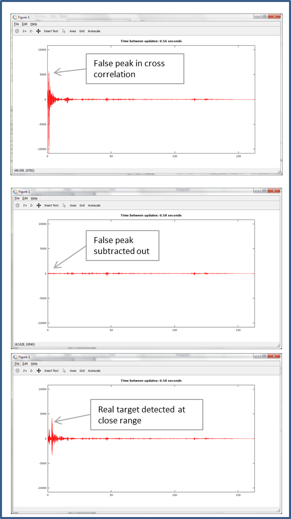
Matched filtering peaks occur at short ranges even though there is no target. This is caused by direct signal coupling between microphone and transmitter, the transmitter 'ringing', or near reflections off of the system housing itself. One simple approach is to ignore peaks within a certain distance, but this causes a blind spot for the sensor. Another simple approach is to lower the chirp power level so that false triggering does not occur, but this limits the range of the sensor. The Bat Sonar project uses two different approaches to combat this issue.
Subtract baseline profile
An alternative that is used here is to collect a matched filter profile when it is known that there are no targets, and then subtract this profile from future matched filter results. This allows detection of targets very close to the transmitter. In my algorithm, the matched filter profile used is a weighted average of a series of samples with no targets. In this way very small but close targets can be identified (3mm).
Varying Threshold based on distance
A thresholding approach is used, where the threshold level is changed based on echo return time. During initialization of the firmware a minimum threshold is determined by sampling the correlation when there is no chirp to estimate the inherent noise level (MEMS microphone and matched filter). The maximum noise over 4 iterations defines the minimum threshold to use at long range. These settings are recalculated when the FM frequency ranges or number of cycles in the chirp are changed.
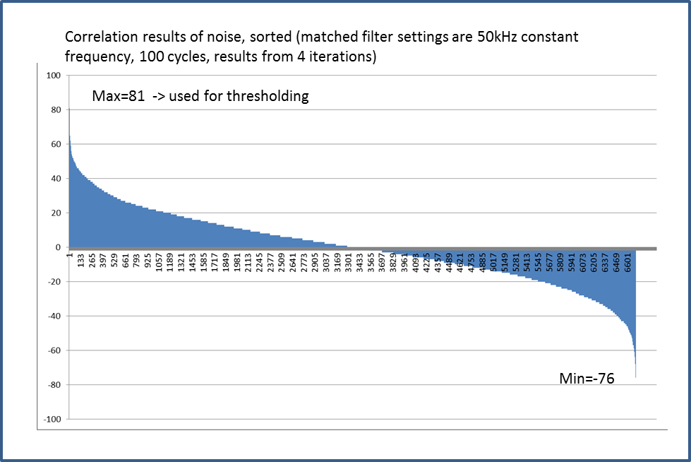
The graph below shows how the threshold is varies. At close range a threshold of 10X is used. Between the two, the threshold is reduced at approximately 1/d where d is the range until it gets to the long range threshold. The 1/d law is used because sound amplitude falls off at approximately 1/d from the source.

Measuring Phase between Microphones
After identifying the target list, the next step is to determine the phase difference of the target using the second microphone. Here we do a local matched filter computation around the peak (32 bits ahead and 32 behind) for each microphone channel and then identify the peak in each. The time delay between these peaks translates into an angle of arrival. Note that this is localized for each target, so we are not calculating the matched filter response completely for the second microphone, only nearby the peaks.

Implementation Details
Some more details that get the system to work in practice.
Calibration
In the calibration phase, the system makes some measurements to use later for interpreting the raw cross correlation data. Calibration is initiated by pressing the SW2 on the FRDM-K64F board when there are no nearby targets. The switch closure triggers a state machine in the software that goes through these steps.
- Measure the inherent noise level in the system. This is done by turning off the chirp output, but still executing the matched filter correlation processing for 4 cycles. The maximum cross correlation value is captured and assumed the maximum inherent noise that will be seen. This sets the threshold for detecting targets at long distances.
- Turn the chirp back on, and capture the cross correlation for 4 cycles over the range that will be baselined (subtracted out). It is assumed that there are no targets in this baseline range at the moment. The 4 samples are averaged using a simple moving average equation (IIR filter).
The start of the attached video shows these two steps in action. You will notice first that the cross correlation graph has a big peak close to zero caused by false reflections and direct signal coupling, then the graph goes flat, during step 1 above, followed by the false peak returning at the start of step 2 above, and then shrinking after subtracting the average baseline in step 2.
40V power supply
The 40V power supply steps up the 3.3v power to drive the piezo ultrasonic transmitter to it's full range. The specification for the transmitter is 30vRMS maximum, which for a sine wave signal corresponds to a 42 volts 0-to-peak sine wave. To drive at this level, a 40 volt supply is used, along with a push-pull amplifier to provide 80 volts peak to peak output drive. Afer some searching, I found an IC for a boost converter that supplies 40v designed for LED lighting.

Setup of Control Parameters
The 'user interface' for the prototype is through the Kinetis debugger. Chirp control parameters can be changed in the Kinetis debugger by changing volatile variables in the code.
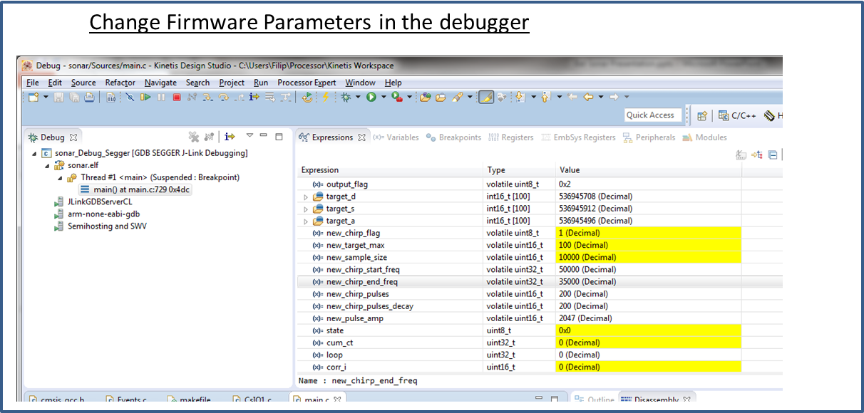
output_flag: 0 is no output, 1 is ascii text serial output, 2 is binary serial output
new_chirp_flag: set to 1 when changing any of the below values – causes recalc of the matched filter terms and other preset items
new_target_max: maximum number of targets to track. Octave files expect 25 to work correctly. Max is 100.
new_sample_size: maximum number of 32 bit words to collect from the mems microphones. One 32 bit word is approx 0.053 inches. 10,000 is max. Must be a multiple of 4.
new_chirp_start_freq: starting frequency of chirp sweep in Hz.
new_chirp_end_freq: ending frequency of chirp sweep in Hz.
new_chirp_pulses: number of positive and negative going pulses in chirp. Must be an even number.
new_chirp_pulses_decay: normally the same as new_chirp_pulses. Can be made larger to account for ringing of the transducer in the matched filter terms.
new_pulse_amp: amplitude of the chirp pulse. 0 is none, 2047 is the maximum.
Octave Output
The firmware outputs the correlation calculation and target information as a set of arrays using serial IO. Octave (an open-source Matlab clone) is used to provide fancy plots and allow further computation if desired.
while (fgetc(stdin) != '\r'); //wait til Octave initiates read
arraywrite(corr0, sample_size, sizeof(corr0[0]));
arraywrite(target_d,target_max,sizeof(target_d[0]));
arraywrite(target_a,target_max,sizeof(target_a[0]));
arraywrite(target_s,target_max,sizeof(target_s[0]));
arraywrite(target_s1,target_max,sizeof(target_s1[0]));

fflush(stdout);  //make sure everything is sent in the cycle
The Firmware waits until the Octave script initiates the transfer by sending a 'return' and then the firmware sends the data. This data transfer takes some significant time so its possible to turn off (by setting output_flag=0 in the debugger to bypass any output).
The Octave script calculates the angle of arrival of each target based on the phase delay and plots an xy chart for each chirp pulse. Also plotted is the correlation graph with each chirp.
Final Thoughts
This is a feasibility prototype built with a number of boards, so its not meant to look pretty. There are also some extra parts on the boards, in case they were needed. For example a 4MhZ clock on the microphone board and a temp/humidity sensor on the power board. The 4MHz clock is not needed since the MCU is used to produce the 4MHz clock signal. The temp/humidity sensor was added as a way to improve distance accuracy, taking into account the air temp and humidity which affects the speed of sound.
Some power supply coupling between the output stage and the mems microphones led me to adding a separate voltage regulator and capacitors to isolate the power.
Further work
Try a tweeter horn for more power and flatter response Switch to this transducer 255-400ST16-ROX with 125db output at 30RMS.
- Take advantage of doppler effect to measure target velocity. Send up chirp and down chirp and measure frequency shift.
- Use an M7 at 240MHz for faster processing.
- Switch detection modes based on target distance and size like bats do. Use fixed frequency for range and period modulation for more resolution at closer distances.