 Rue Mohr
So, I decided to build this 1 channel version of the power supply, and although I'm not directly documenting it, its research is going to be used in THIS power supply.
What I did today: (its not tommorow till I'v slept)
For the 1 channel supply I worked out I need a switching converter, this means building another one (the 250Khz one isn't going so hot) with whatever compromises are needed to just get it working. The goal for this one is to operate at about 40Khz.
Thinking on the pwm genorator schematic, I decided to try using a 4060 clock/divider chip, this would give me an oscillator and a divider all in one 16 pin package. (the last circuit took two, a 4069 for the osc and a 4013 for the dividers) As well, the 4060 has an array of dividers that would give me more options on the crystal I use.
After pouring thru all my crystals and doing lots of division I worked out that the best option was a 6Mhz crystal with a divisor of 128 which gives me about 47Khz
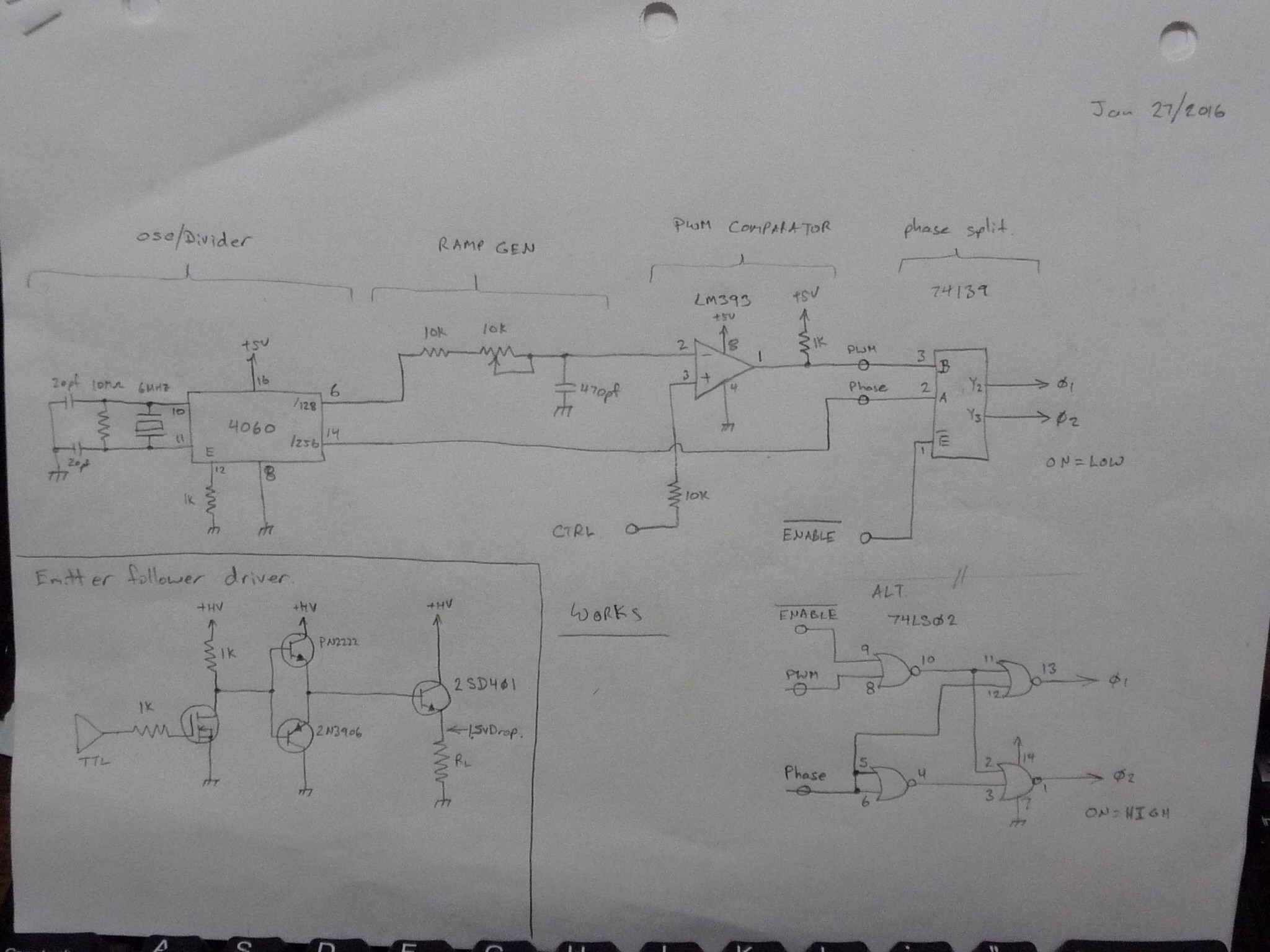
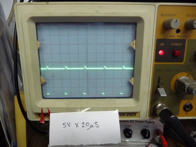
The pwm is generated in the same way as the last circuit, and while building it I noticed something interesting:
** If the LM393 is used with the ramp on pin 2 (-) and the control on pin 3 (+) its output is clean, BUT if you reverse the two pins (to, say invert the pwm) there is significant ringing on the output.
This is probably what lead to some of the difficulties I was having with the previous circuits, my addition of the disable line required inverting the pwm, so I compensated for it at the comparitors inputs.
--
I decided to try something new with the phase splitting circuit, and I used a 74139. the TTL output it messy, but it does work. That said, when I started playing with driver circuits, I had to invert the outputs, and ended up using a circuit based on the 74LS02, which actually gave a much cleaner output.
--
Then I started playing with driver circuits. When I built the power board for this 'quick and dirty' supply, I used PNP transistors in common emitter mode.
Playing with various configurations, I was unable to get any common emitter amplifiers to give a nice output, all of them had timing distortions at low duty. It seems in order to switch them off, you have to reverse bias the BE junction with atleast 1V.
The idea struck that the common emitter amplifiers performance was SO terrible that I could probably get better output from a common collector amplifier, so I tried it...
Its a bit laborious, you need to convert the ttl to full swing voltage, which I did with a 2N7000 and pullup resistor, and drive the base with some current, which I did with a PN2222/2N3906 totem pole pair. The output was GREAT, like, really great.
It loses 1.5V from the supply rail to the load, thats equiv to a 0.3 Ohm mosfet at 5A, which is about where I'd be at by the time I found a P channel fet with a low enough input capacitance to use at high freq.
--
What did we learn today?
Today we learned that capacitance really sucks!, weather its in an LM393 op-amp, or a power driver transistor, if you have an input that fighting with an inverted output, even 40Khz waveforms are going to suffer.
I may change this quick and dirty supply to use a set of NPN transistors in common collector mode. I could use N channel fets in common drain, but I'd need a bias votlage about 5V higher than my top rail, which I CAN do }:], but I don't want to.
Its 2:30am, goodnight.
--
oops funny what you miss at 2:30am, the output polarity is wrong,its supposed to go from 0-50% duty, need to redo that phase splitter as a NAND circuit :)
more images:

Discussions
Become a Hackaday.io Member
Create an account to leave a comment. Already have an account? Log In.