 roberts.trops
Since this was a quick project, I didn't spend much time designing main board and laser driver PCBs. As a result the PCBs have several bugs that I fixed in after fabrication. I haven't fixed these problems in PCB designs and I probably won't do it any time soon. I don't want to publish half baked designs, but I think the schematics are "ok". Main board and laser driver are separate boards to just to simplify debugging.
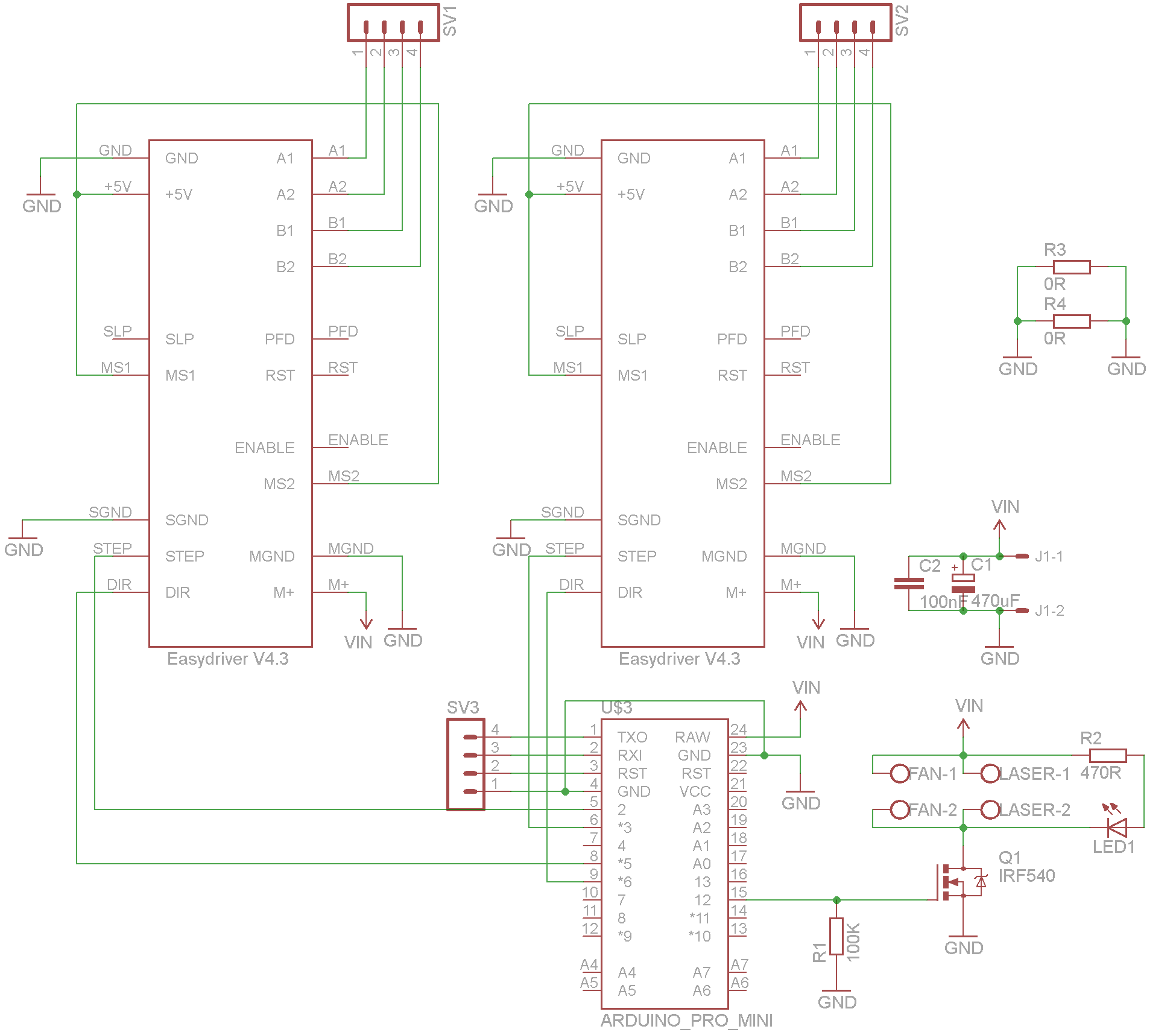
Main board
The main board connects arduino with motor drivers and switches laser and smoke fan (the one near laser). One thing should be taken in account when using this schematic. If you laser housing has contact with the electrical ground (for example the structure which is connected to electrical ground) the fan and laser will be switched on, because this connection will bypass the MOSFET. I simply isolated laser housing from rest of the structure.
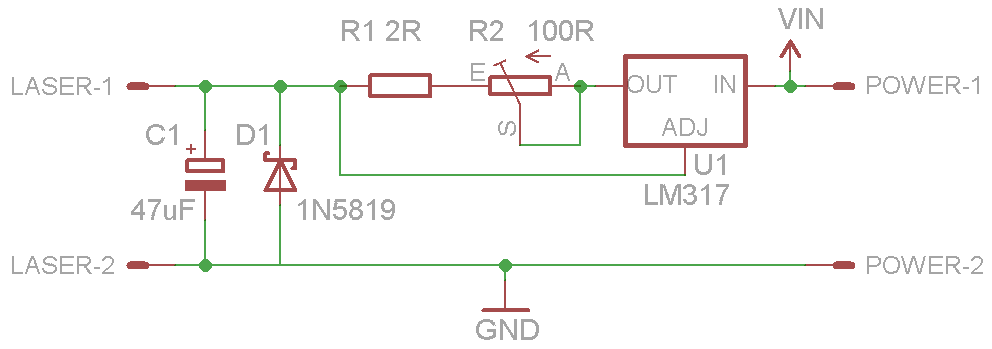
Laser driver
The variable resistor R2 can be less, in fact it should be around 10 ohms in order easily adjust current. Be sure to test this circuit before connecting to laser diode. I used laser diode from DVD writer so the driver should be adjusted to about 200mA. I added larger radiator and placed near the inner fan (inside PSU case) for better cooling. Inner fan also cools motor drivers as well, but it is not essential.
The whole thing is powered by 5 - 12V 1A adjustable adapter which is set to 9V. So far it works great. I haven't noticed any glitches or weird behavior. If you have any questions or ideas, please feel free to add a comment.


 AltMarcxs
 Joseph Lavoie
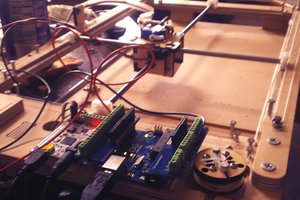
 Zachary Marlow
Thank you! I'll try to use the program you have suggested!