Close
0%
0%

grbl "Man in the middle" CNC jog pendant

A proof of concept ultra-low cost jog (and other gcode commands) control pendant for grbl CNCs. Concurrent with PC serial! DIY macros!

Similar projects worth following
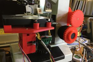
I am testing steppers in the strainwave gear with timing belts project and a grbl breakout is an ideal way to achieve acceleration-controlled rotation to test the torque the gear can achieve.

I got fed up having to connect the grbl Arduino to e.g. Universal Gcode Sender just to make a single motor rotate a bit. So I asked if there's a way to "man in the middle" control the steppers on the Stack. Then I went away and this is what I have come up with to start with.

At the moment it's just for rotating a single stepper in a gearbox. But if you look at the code you'll see the approach would allow you to send any grbl command based on any input you can implement. 

There's no implementation of the proper jog commands yet, I'm using rapids and getting the results I need for my tests. However if you plan to use this in a CNC build I suggest you implement the proper jog commands so you can resume work easier. Also either don't trigger any inputs while the machine is being sent a gcode file!


The current version also tells the PC gcode sender what it told the grbl Arduino and prefixes it with a "P" for pendant:

Please go ahead and build on this to suit your needs. Add joysticks, axis selector rotary switches, reset and home buttons, coolant start/stop, laser on/off switches.

  • 1 × Arduino Nano (or other 328P version) In addition to the Arduino that is running grbl
  • 1 × 4 wires with dupont female connectors on one end Will be 5V, GND, Rx, Tx and connect to the grbl breakout header pins
  • 1 × Rotary encoder and dial/knob You choose. One where the pin order is COMMON, A, B works well with the Arduino Nano's adjacent GND, 2, 3 pins

  • 1
    Attach encoder

    Solder or connect it in some other way so that A and B are connected to digital 2 and 3 on the Arduino and the encoder common/ground pin is connected to Arduino ground/GND.

  • 2
    Attach wires

    We'll use the USB cable from the computer - check that your pendant Arduino uses the same connector as your grbl Arduino or change the cable.

    For the remaining four serial wires between the two Arduinos, you need to connect 5V and GND together. Then connect the grbl Arduino Tx to the pendant grbl softSerial Rx, probably digital pin 10. Do the same for grbl Rx to pendant softSerial Tx.

  • 3
    Upload the code to the pendant Arduino

View all 6 instructions

Enjoy this project?

Share

Discussions

Koenraad wrote 11/02/2022 at 18:55 point

Hi,

Where did you put the code for the pendant arduino?

Greets,

Koenraad

  Are you sure? yes | no

AlejandroVaR wrote 08/08/2022 at 22:49 point

Dear Sir,

I have to say that this is an outstanding piece of work, as a solution to the lack of a propper Pendant, it is simple yet extremely clever. Once developed thanks to your idea and example, It allows to controll the CNC with almost any G-Code command over only 1 wire and GND. Congratulations on this project! 

  Are you sure? yes | no

envelop wrote 05/11/2020 at 19:56 point

Hi Simon, 

I tried your project. But I have some doubts and questions. 

First of all . Do I use 2 usb cables ? 1 for the GRBL arduino and another one for the pendant ? if not , I need to connect the grbl arduino to pc with USB cable in order to operate my cnc. But then I can not see the pendant arduino serial monitor, because the pendant arduino is then not connected to pc, only with 2 wires : tx to rx and visa versa. 

second : if my grbl arduino is connected with tx and rx to the pendant, I will get an error message on the grbl panel. saying it's locked, and I can not use the keyboard jogging or reset it either. 

I have connected 2 usb cables . 1 to the grbl arduino and 1 to the pendant. the grbl on com 3 and the pendant on com 6. I start my cnc program. I use grbl panel as my GUI, and connect cnc on com3. Then start arduino program on pc and connect pendant to com6. works fine. When I open the serial monitor , it states that it is connected to the grbl arduino. and when I rotate the encoder there is code visible on the serial monitor, but the grbl panel , nor the machine is responding or moving. 

Appreciate your comments on this. 

  Are you sure? yes | no

Similar Projects

Does this project spark your interest?

Become a member to follow this project and never miss any updates