 Matthew D
One of the interesting things about the RCA 1802 is that you can add a lot of digital I/O pins without doing memory mapped I/O.
Ok, let me step back a little. I am learning this as I go so I might not be quite right but this is my understanding. On most computers I am familiar with I/O is done by mapping the ports into the memory address area of the computer. So, a serial port is given a memory address and then bytes are written and read "from memory" at that address as far as the uP is concerned. The uP puts the address on the address bus and then reads or writes from the data bus.
So the circuit design is done in a way that some of the address space is wired to non-memory circuits.
The 1802 is interesting because it has a set of instructions that will put the value of the data bus into memory after setting a value onto three special pins (N0, N1, and N2). So you get a separate 7 bytes (there is no instruction for 000b) of address space for I/O that has its own special machine instructions.
The original ELF article describes a system where the use of the N pins is limited to "is N2 set?" or "is N0 set?", which limits to 3 bytes. I am going to build my ELF to have a little more developed I/O system so that I can add a full set of I/O ports if I get around to it. (This should only require one more logic chip.) The switches and LEDs will still be put at the same I/O address as in the article so that I can run some of the programs intended for the ELF.
Here is a hand drawn schematic of a representative I/O port.
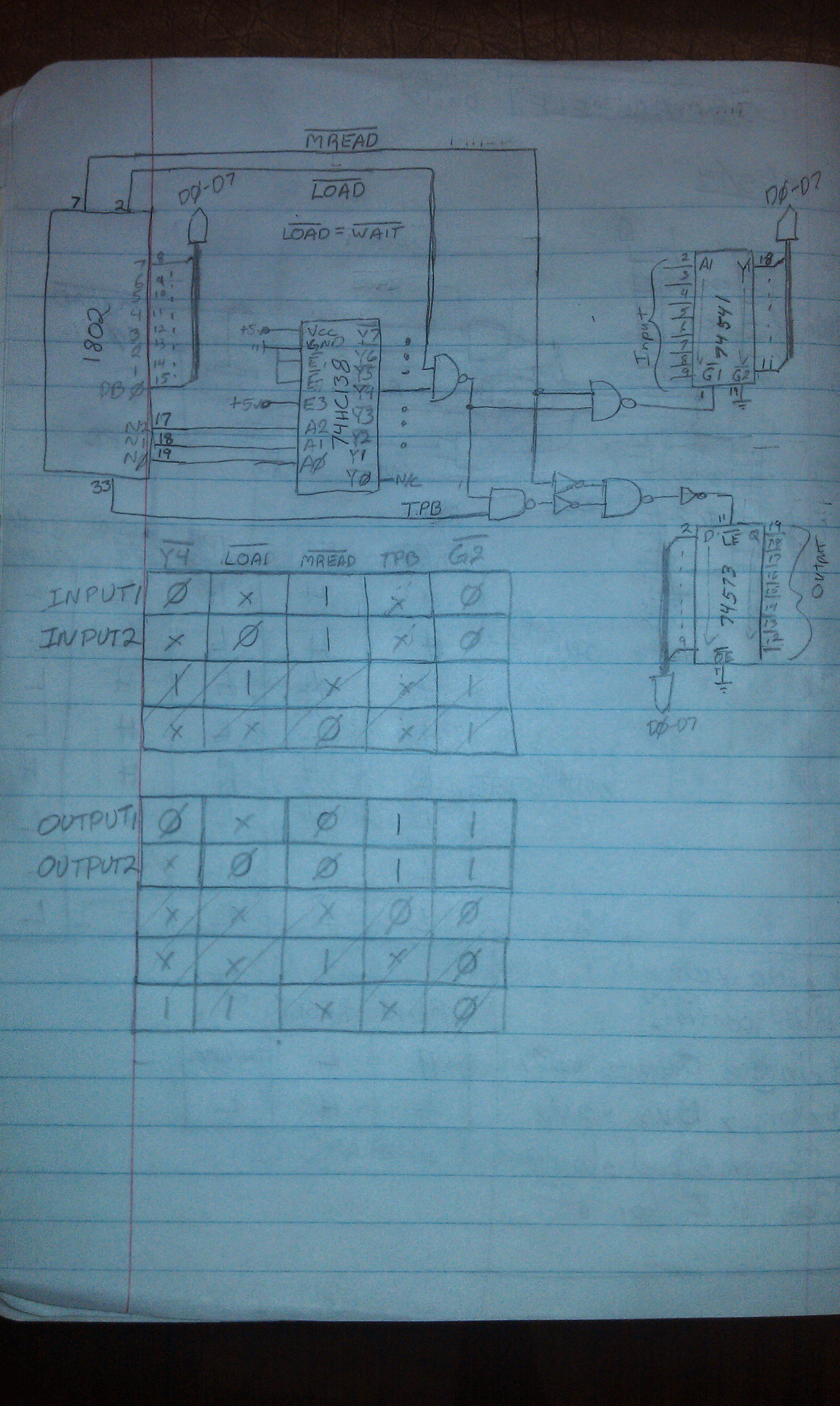
This scheme will use one 74HC138 to decode the N pins and then 4 74HC chips per port (74HC00, 74HC04, 74HC541, and 74HC573).
In the end this may be overkill, but it was fun to work out and hopefully I don't regret it when debugging starts.
Discussions
Become a Hackaday.io Member
Create an account to leave a comment. Already have an account? Log In.