 AVR
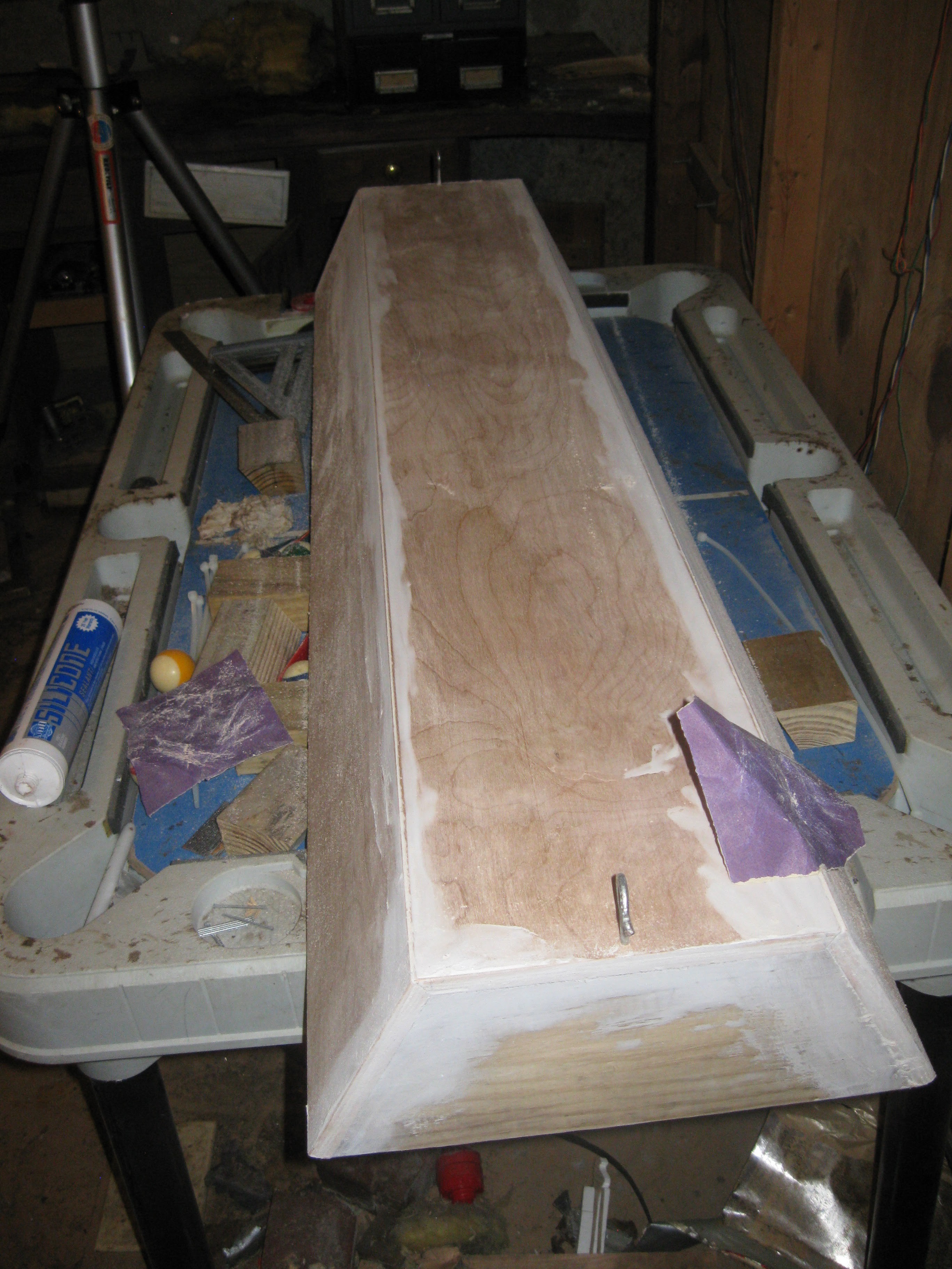
AVRThursday of this past week I got a bit more done. I sanded and painted the grow light casing (see previous log) smooth for painting, and painted it. I also conducted a circulation test of the NFT system in the basement. First off the light, I started by sanding the edges and caulking down with sand paper by hand. I tried to sand it all down smooth but the caulking is tough stuff, I did the best i could before cleaning it with a dam rag for painting.
Sanding the grow light casing:
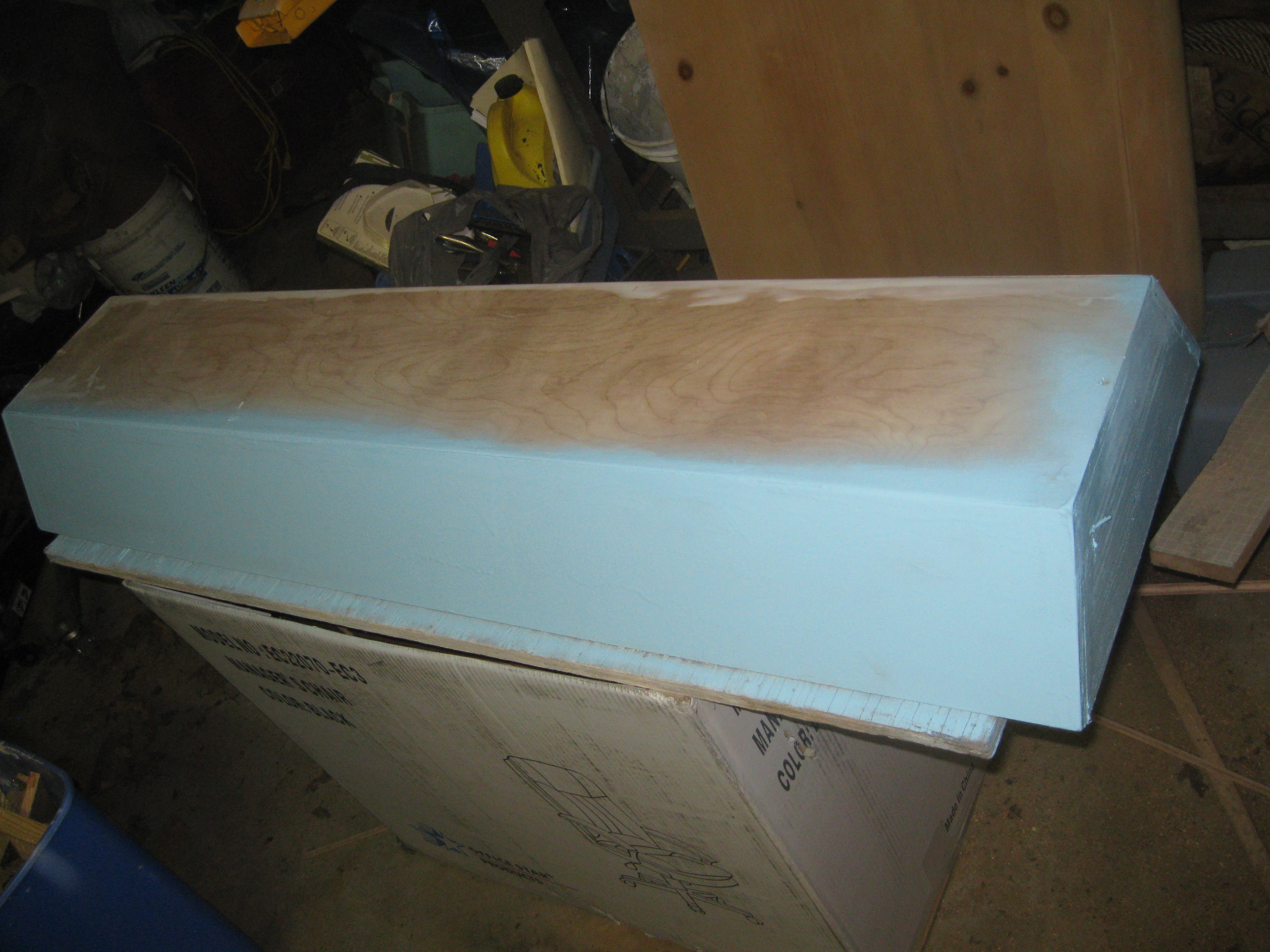
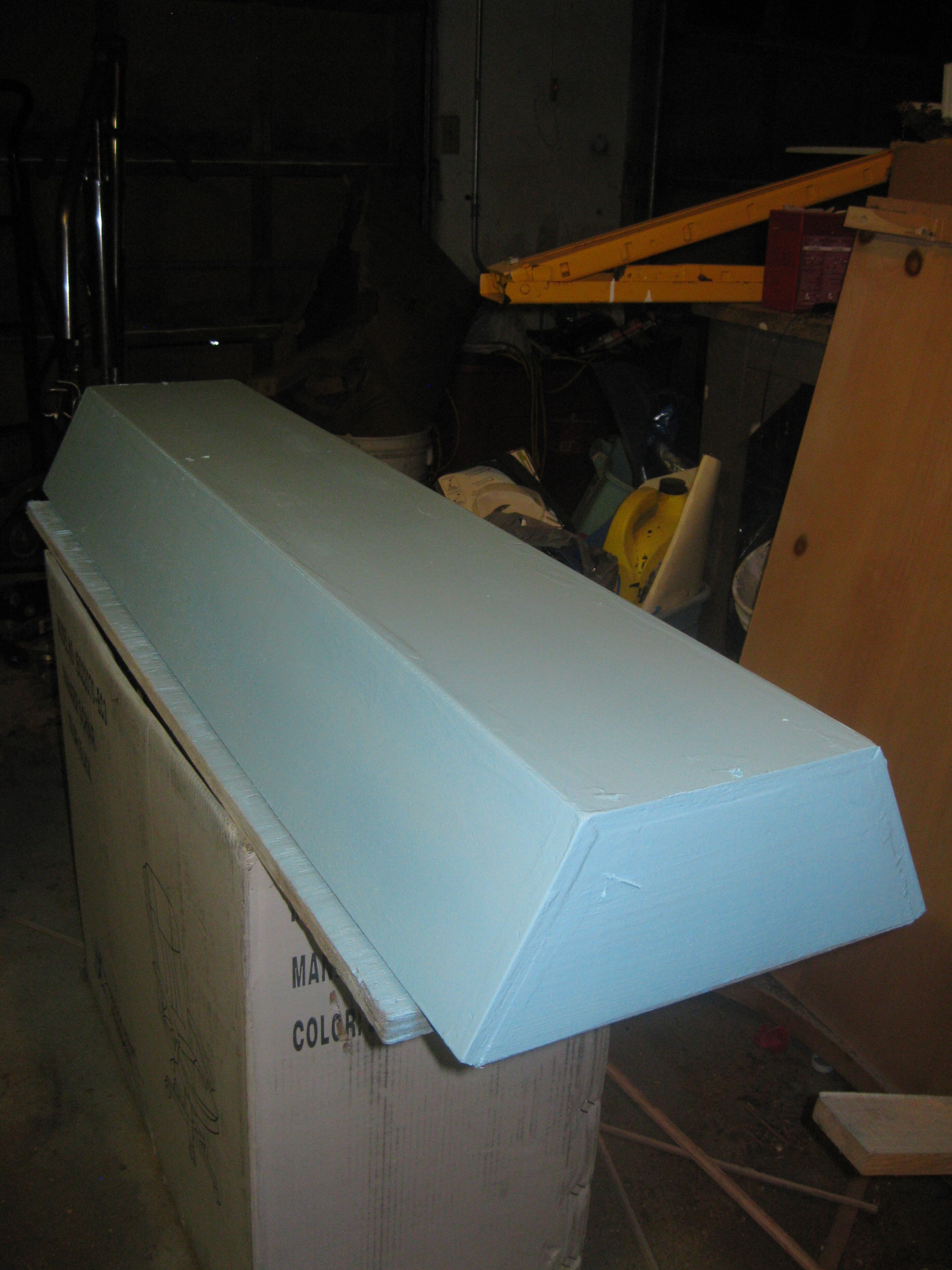
After I completed sanding and cleaning the dust off I brought the case into the garage for painting. I set up a simple table with a piece of plywood and an old card board box for painting. I painted in stages doing multiple coats over a few hours, this is so the paint doesn't drip and form drip marks all over the surface. I used rustoleom spray paint since its good on wood/plastic/metal and its cheap.

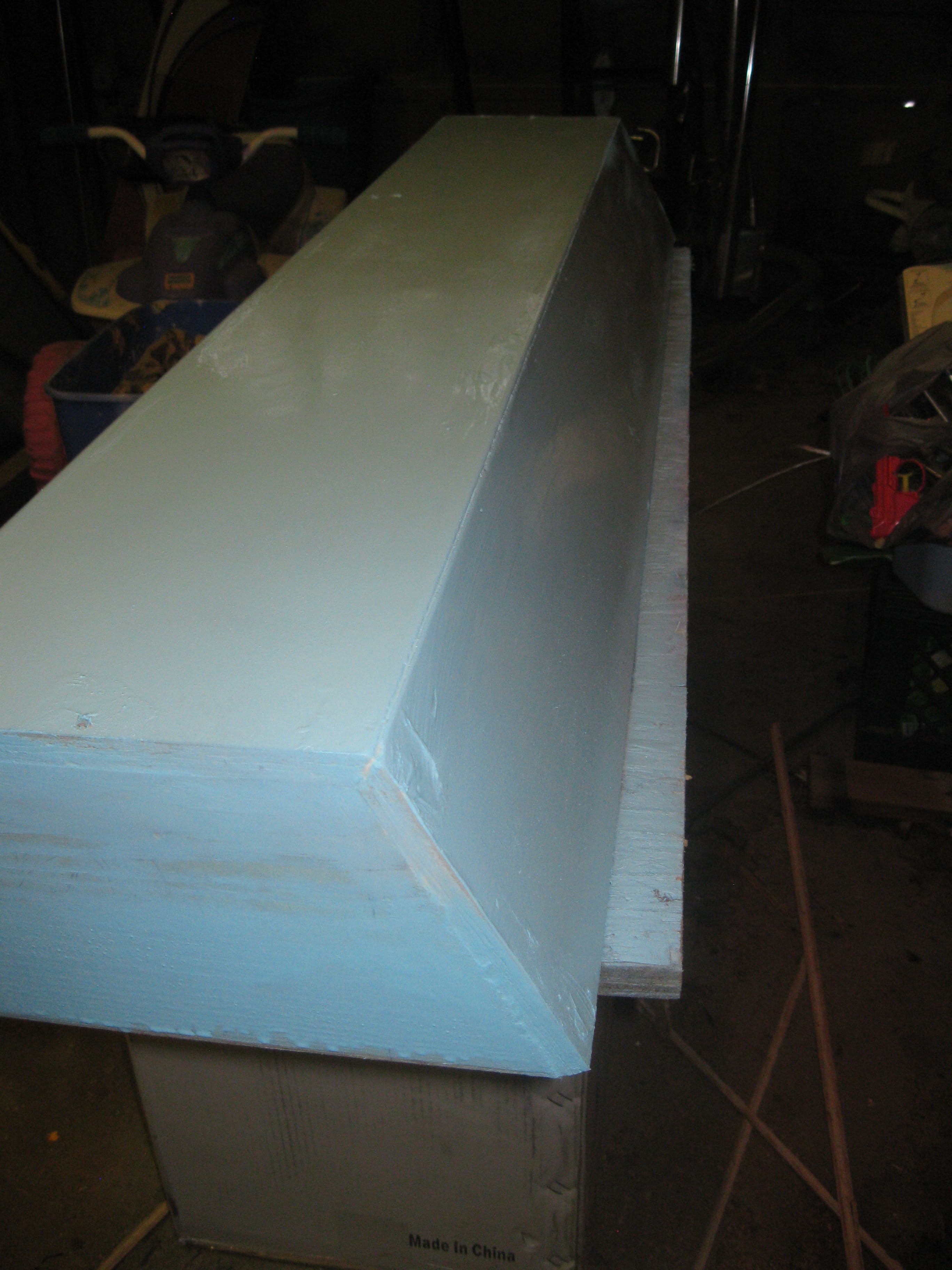
One side and end painted, with the top and other side to go.
Top and and one side painted with one coat.
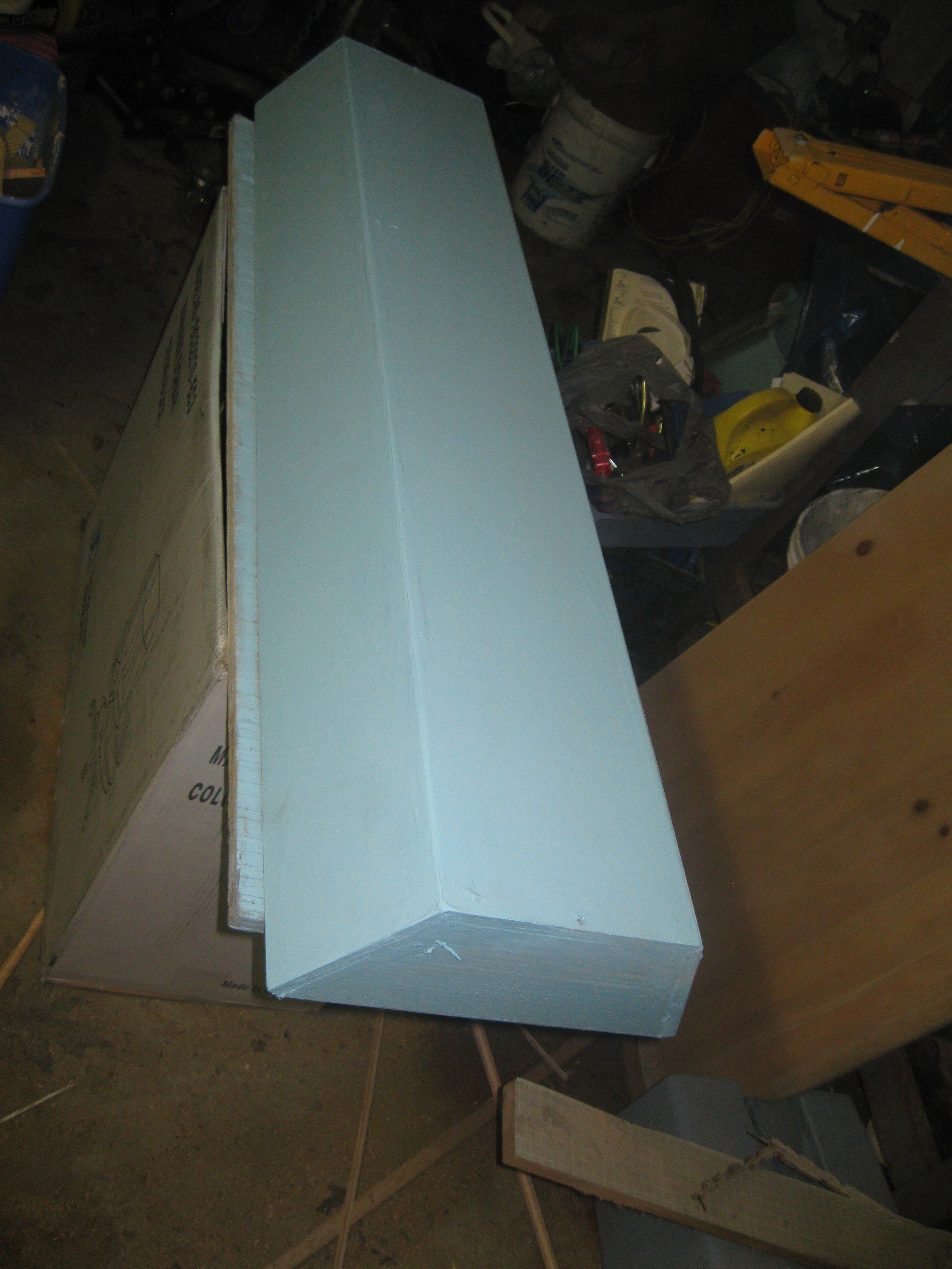
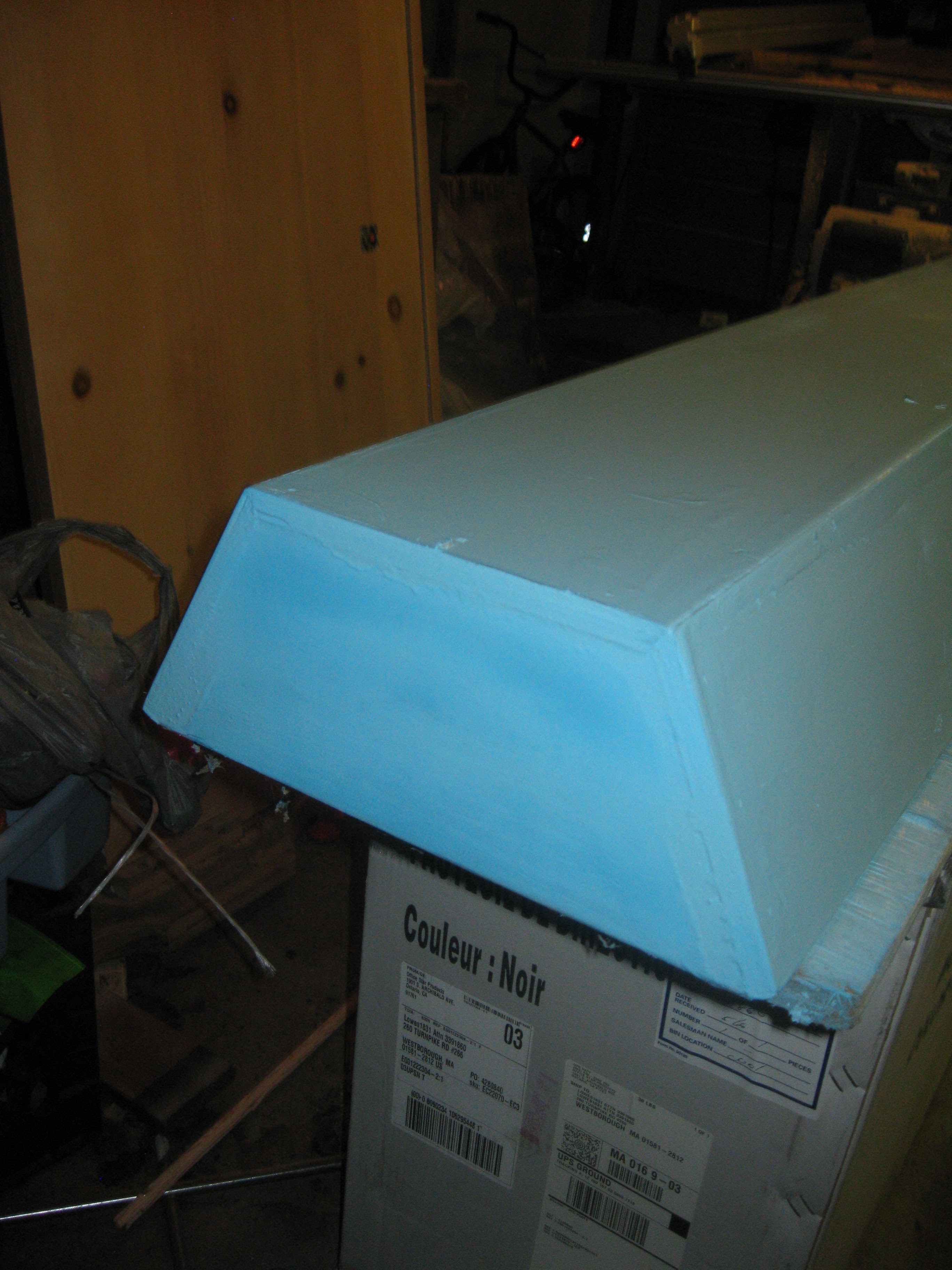
Other side painted, this color is very nice the pictures really don't do it justice!
Opposite end painted with first coat.
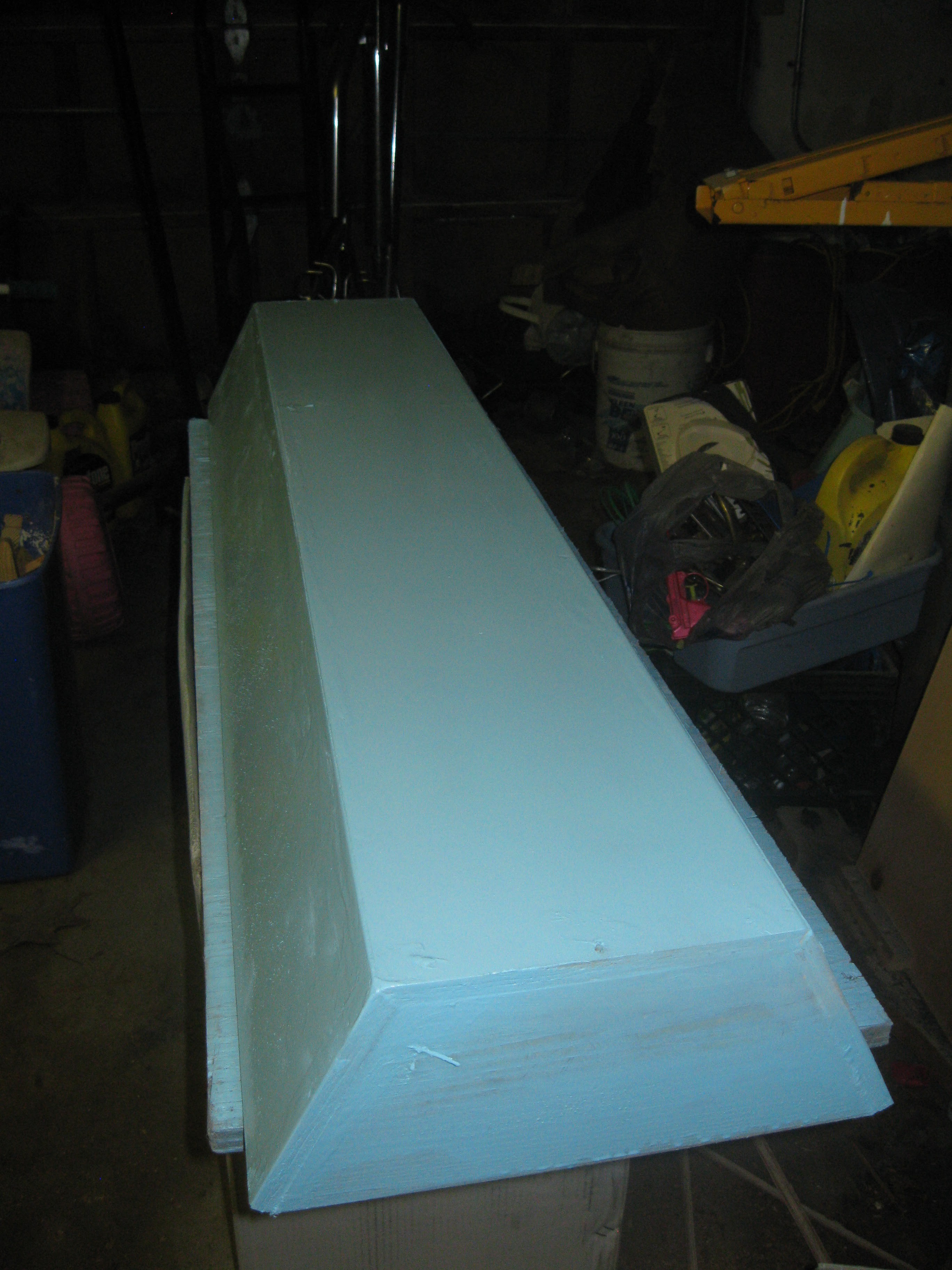
Second and final coats of paint:
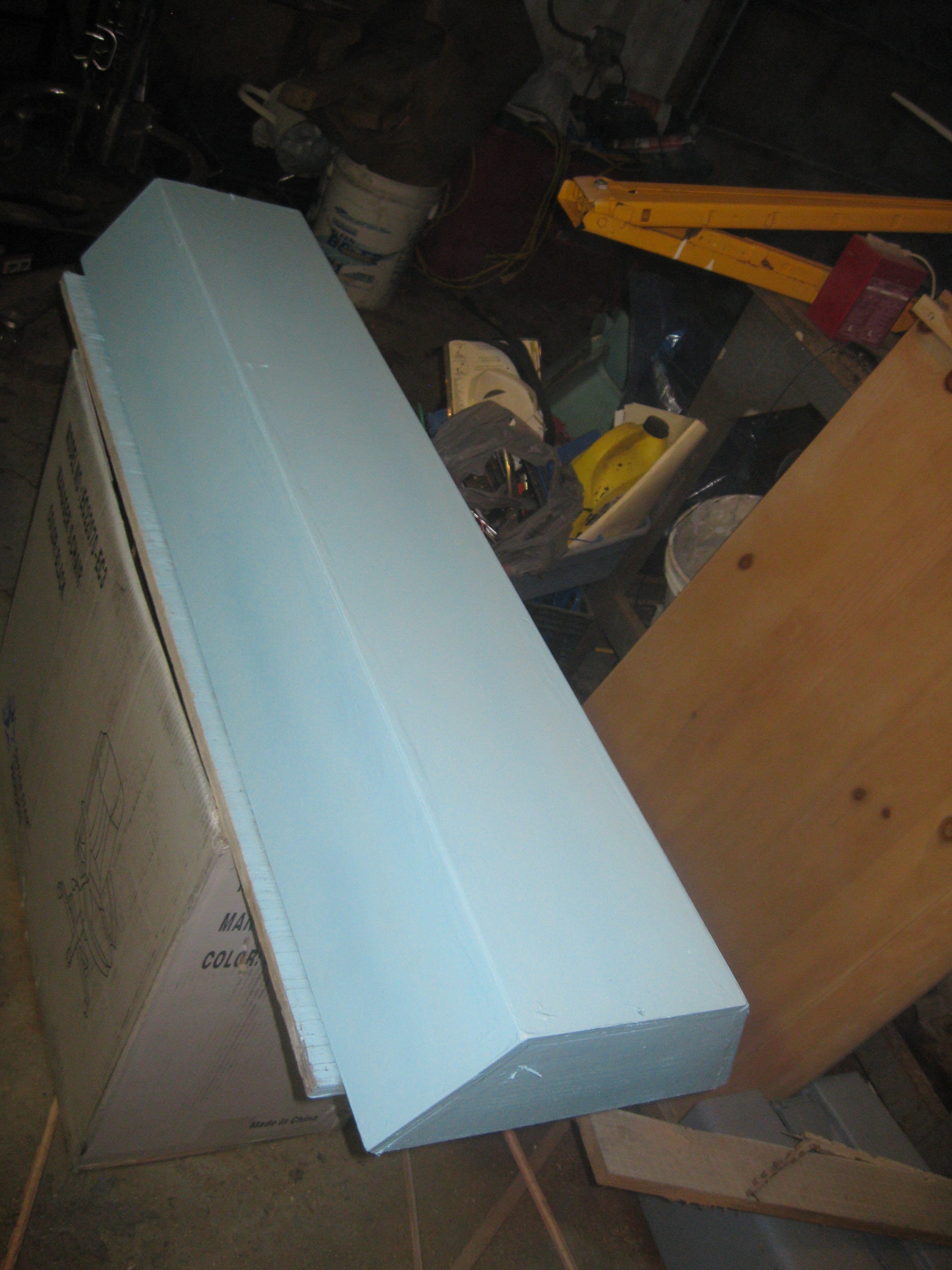
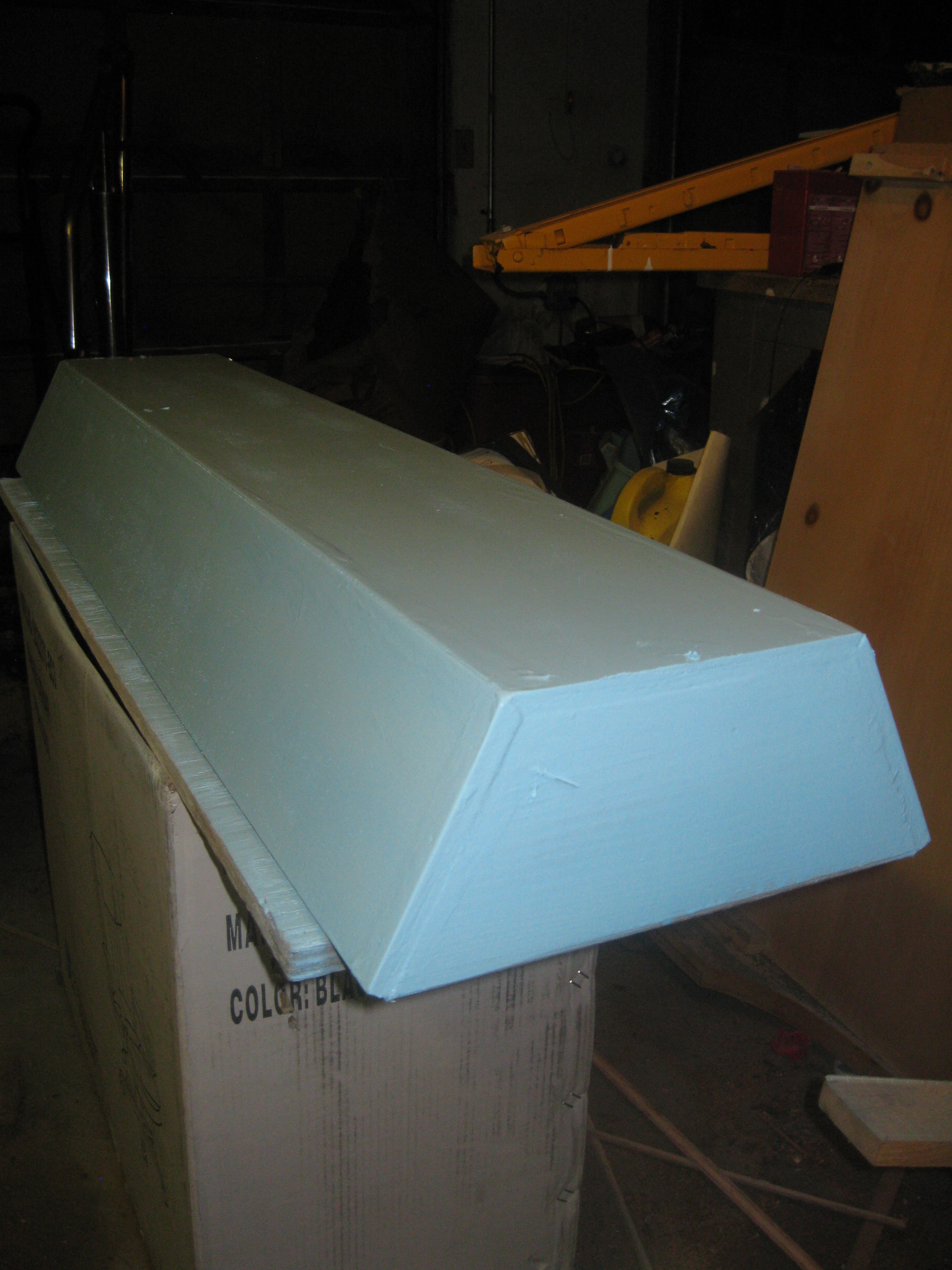

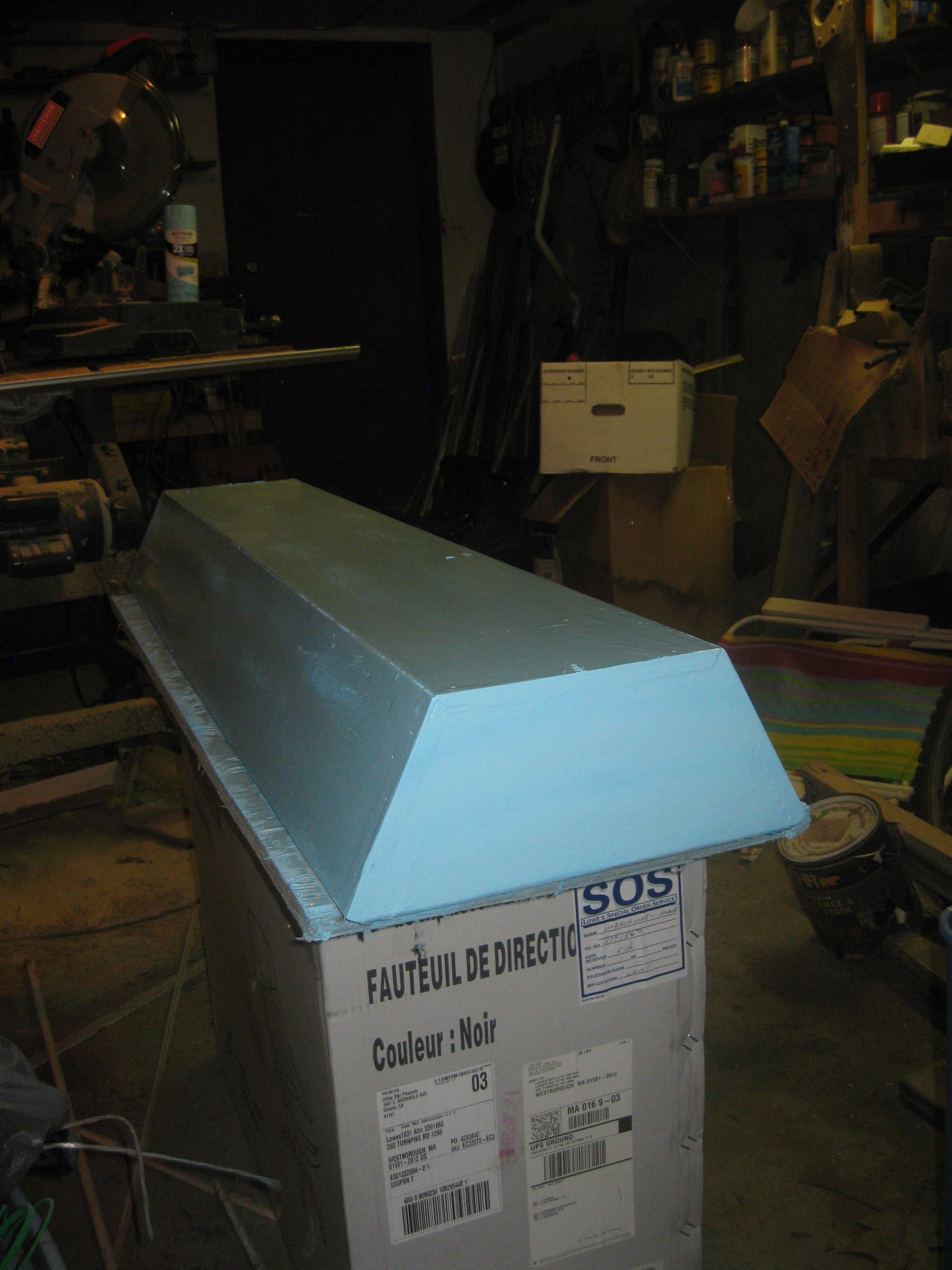
Painting tool about three coats and I didn't even use up all the paint in the can. The first two coats were heavier than the third, overall it came out pretty good. I need to do some more painting on the inside before I install the lights. Before I was thinking of plating the inside using tin foil or with a reflective mylar space blanket, to simplify things I will be painting the inside white. The color white should be reflective enough given that almost the entirety of the inside of the case will be lined with LED strip.
Moving on with the NFT system test. Before getting too excited and moving all my cramped plants into the new grow system I decided to conduct a test of the pump circulation system. I wanted to make sure the pump I am using can handle pumping from the reservoir into the input manifold. Setting up the NFT system with water for the first time is sort of a process, first I'll talk about the setup/function and what I found out about my chosen design.
The setup as left after the silicone sealing of the end caps. It was good it was still mostly dismantled, installing the reservoir in place beneath the until requires lifting the frame, its a lot easier with everything removed.
Flow rate sensor removed from pump tubing assembly and installed to the input manifold. The fitting on the end of the flow rate sensor adapts from 1/2" threads to a 1/2" barbed end for attaching to the tubing on the submersible pump.

To get things started I began with setting up the reservoir internally, an airstone in each corner almost and the pump centered in the middle, secured to the bottom with suction cup feat. The tubing for the airstones, pump power cord, and pump tube all fit through the same hole in the top.
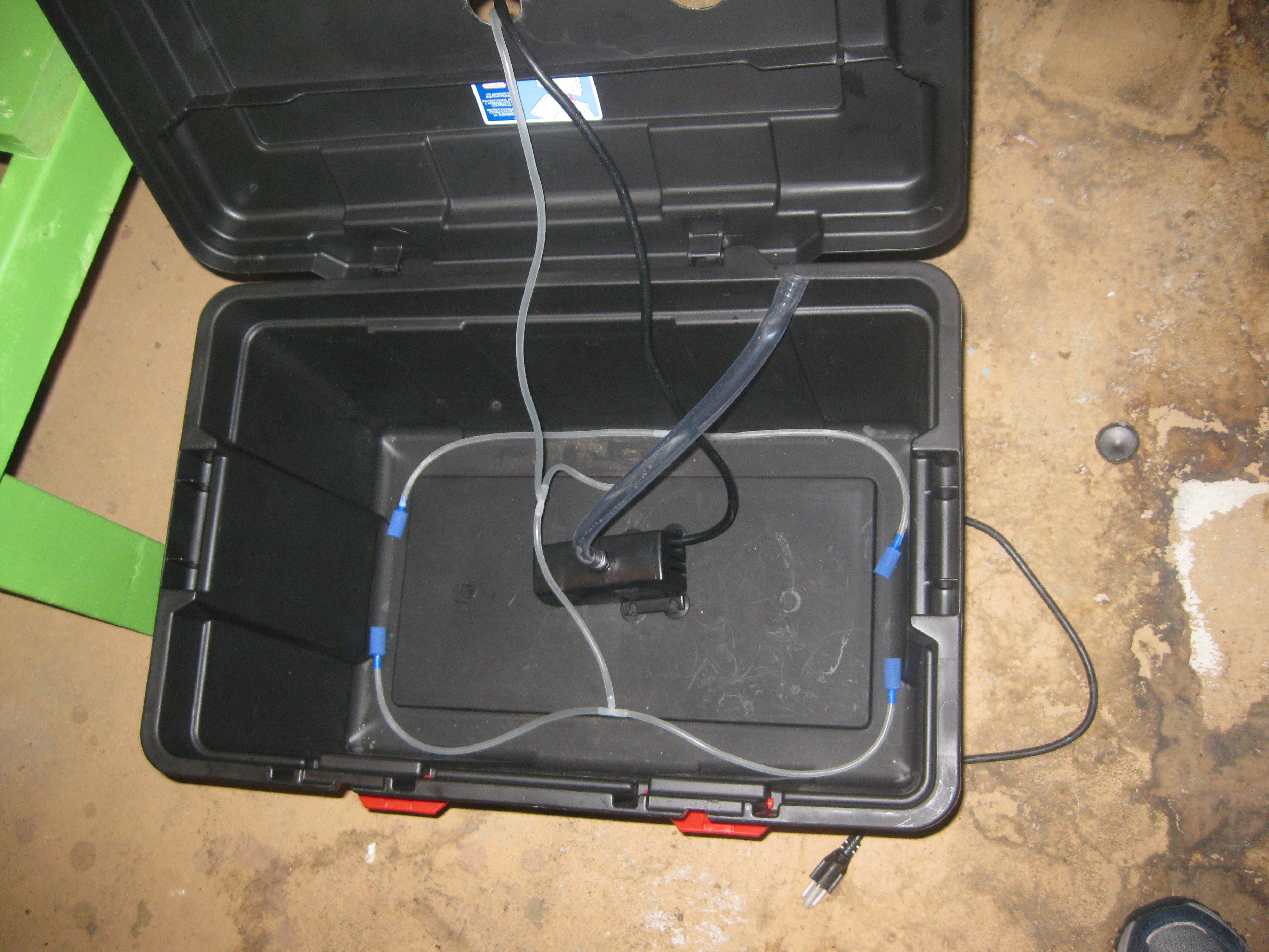
Next I filled the reservoir with 5 gallons of water, everything inside got swished around.Later a better method for securing the pump and airstones will have to be worked out, possible using silicone as a glue to secure the tubing in place on the bottom. The reservoir has to be filled before hand at the moment since there isn't an input pipe yet, later I plan to add another 1 1/4 " pipe for adding more water/nutrients/boosters to the reservoir.

Next I slid the reservoir beneath the frame. Since the drain manifold is built into the frame the frame needs to be lifted up to slide the reservoir underneath.
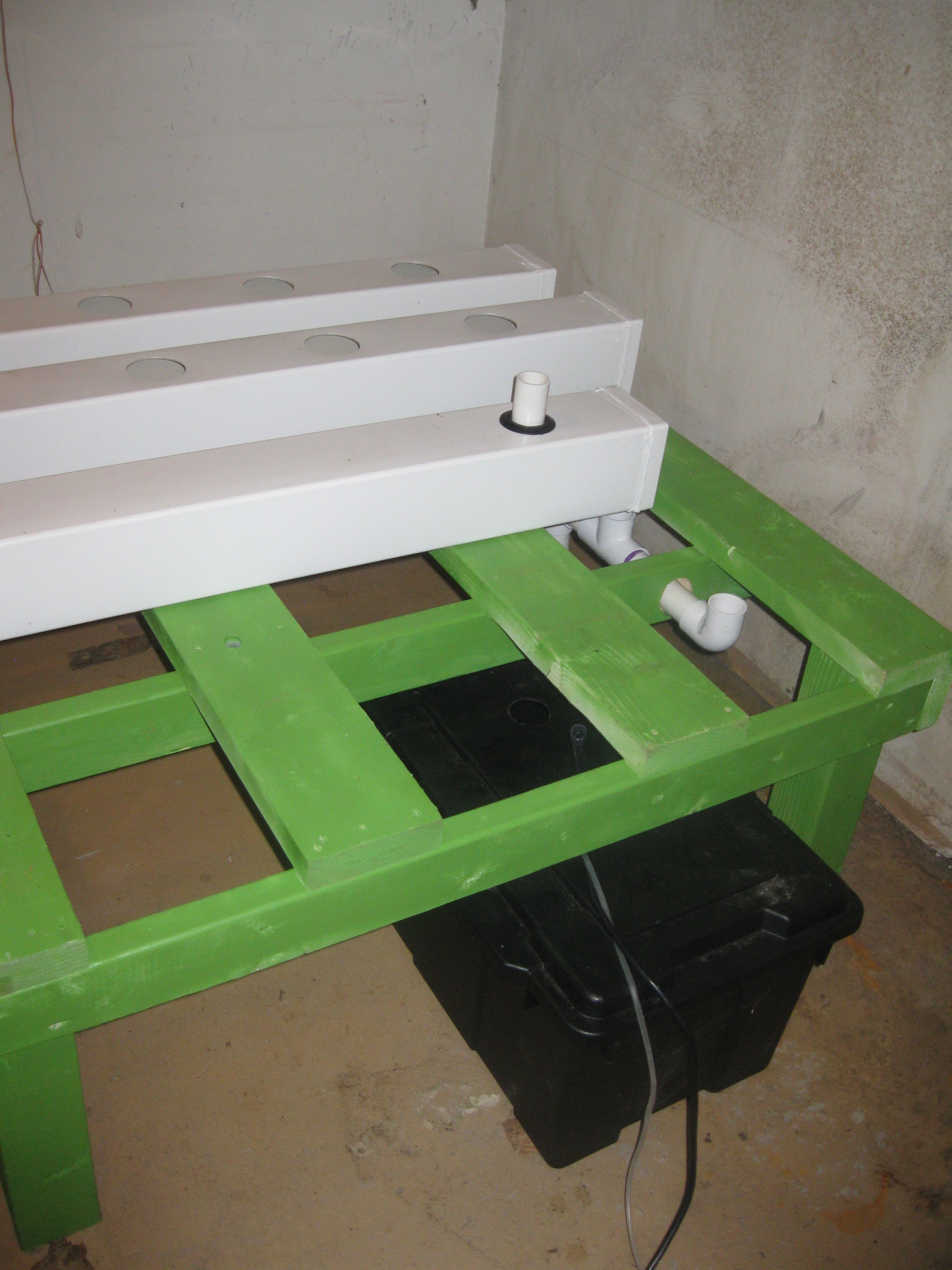
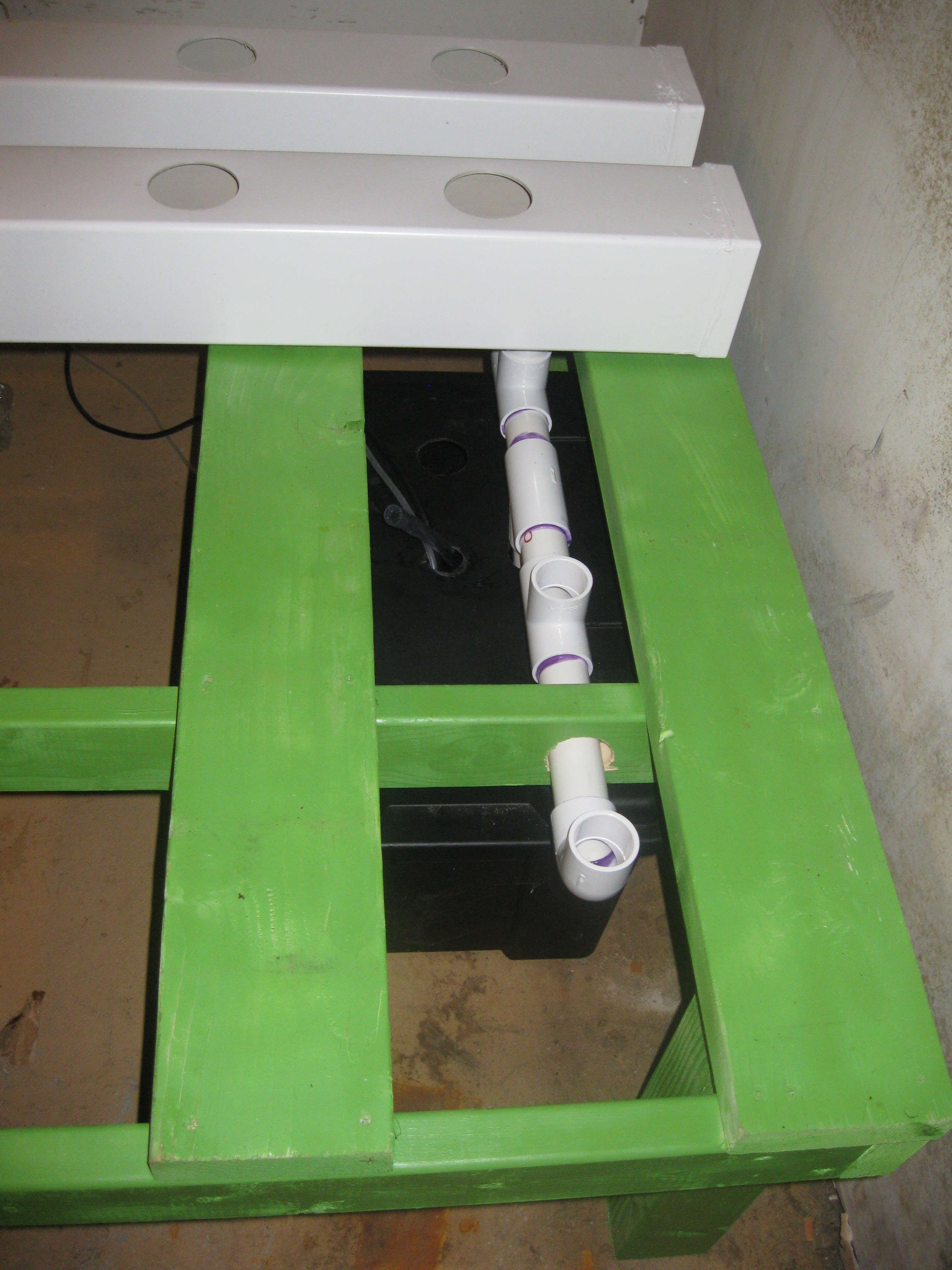
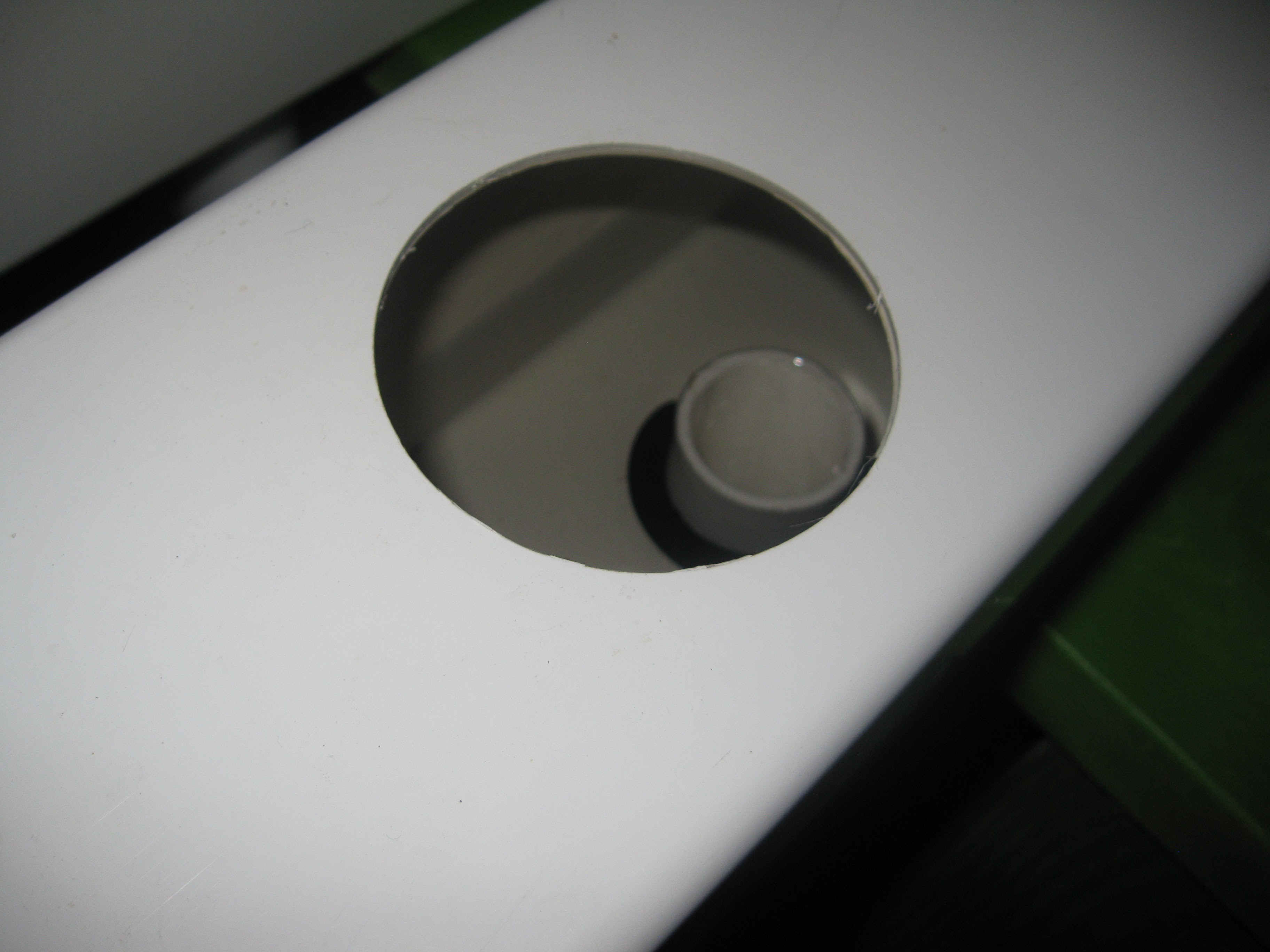
Reservoir installed into place, with the drain manifold exit protruding directly through the hole cut for it on the top of the reservoir.
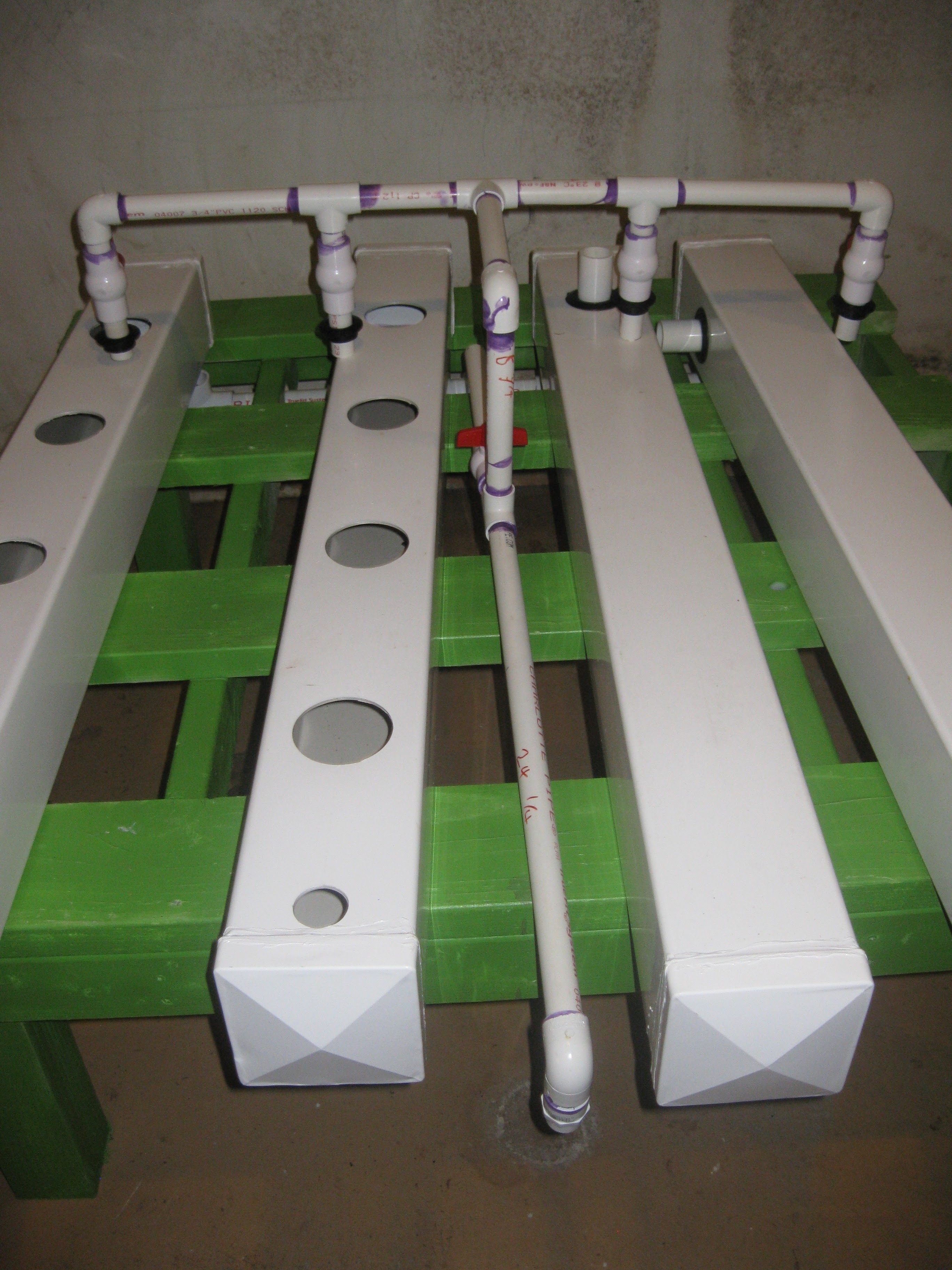
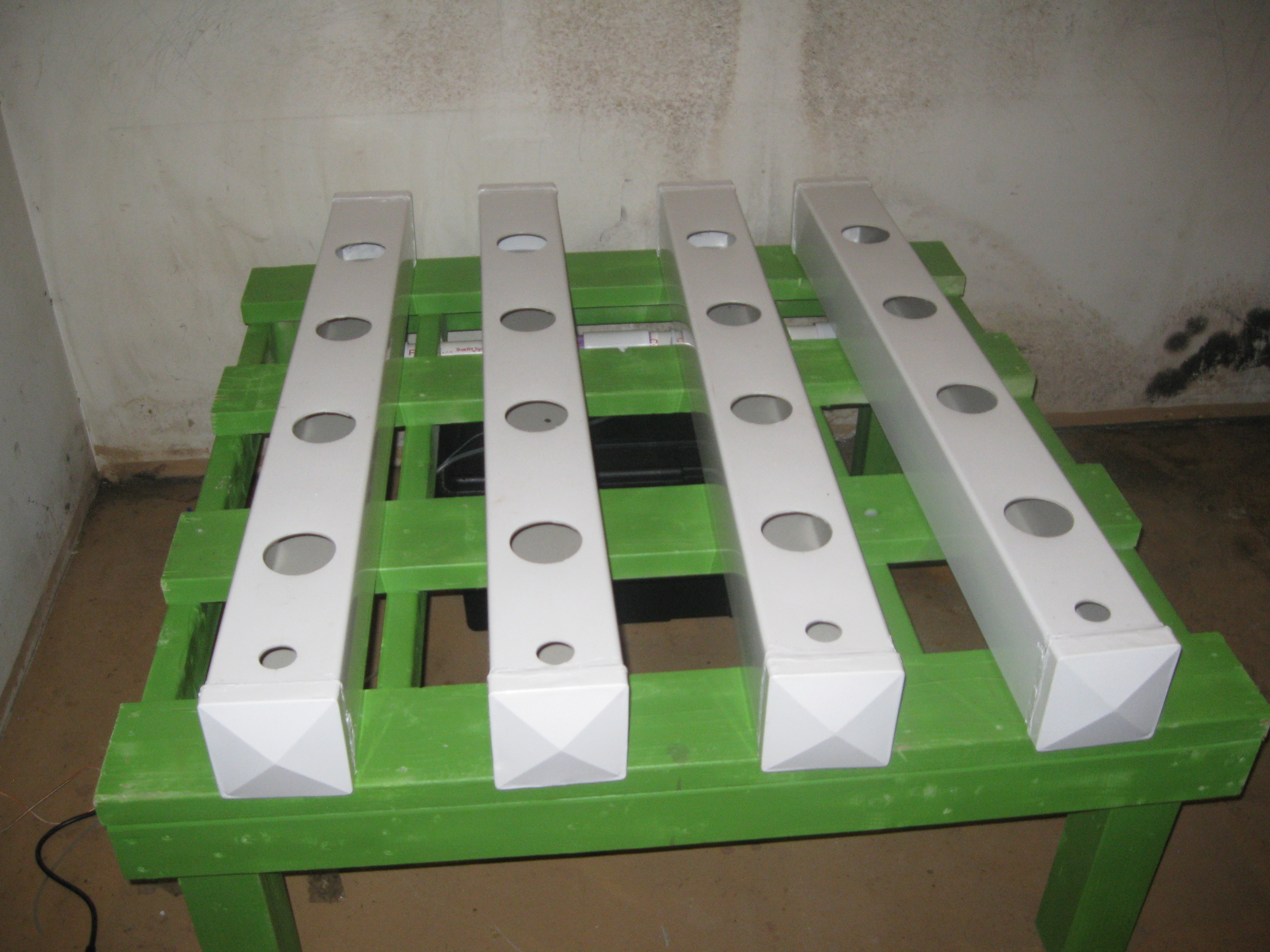
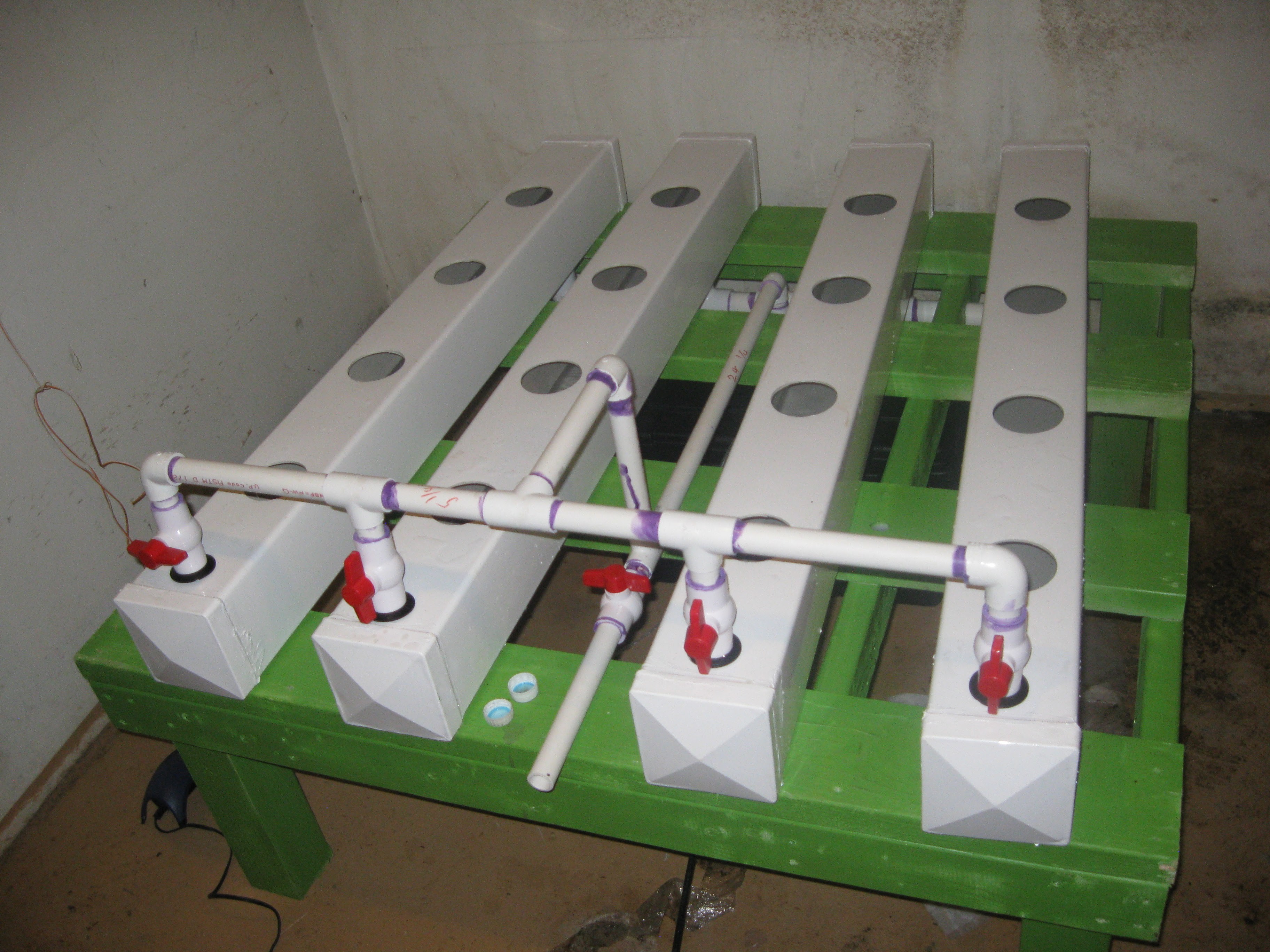
All four fence post grow rows installed into place after installing the reservoir. The next step was installing the input manifold and connecting it to the pump. After the input manifold was in place, valves on 3 of the four rows were closed before starting the pump, each row disabled at the start were enabled one at a time starting after the first row was filled and running into the drain manifold.
Water inside the first two rows
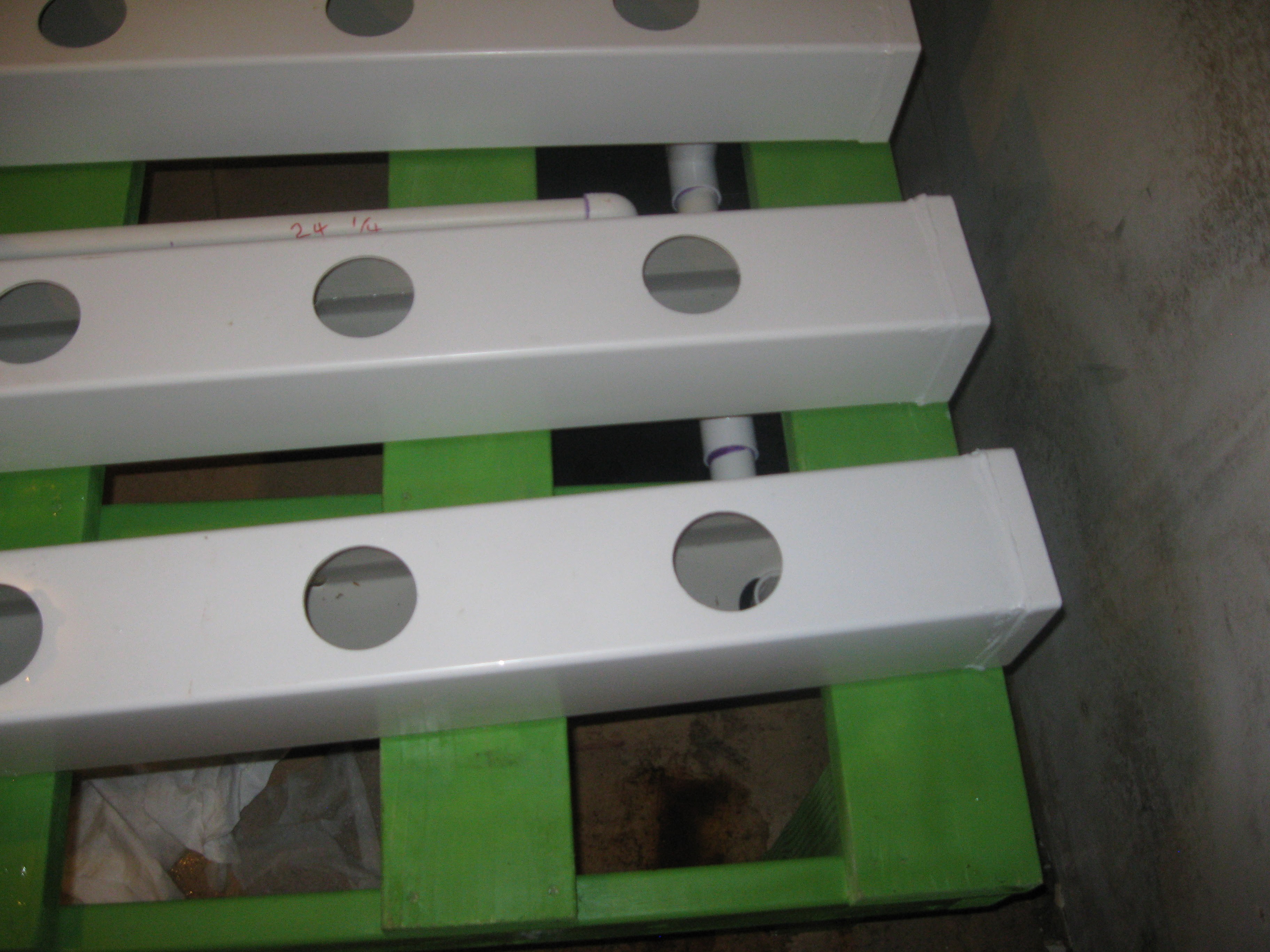
Close up of the water draining into the drain manifold on one of the rows.
After attempting to get all four rows filled with water, I discovered a problem. It seemed the pump was too weak to pump the water into the manifold. After some investigation and testing different rows by opening and closing the valves, I determined that the pump only has enough power to run half the system. A larger pump will be needed to get the system up and running but its not the end of the world.
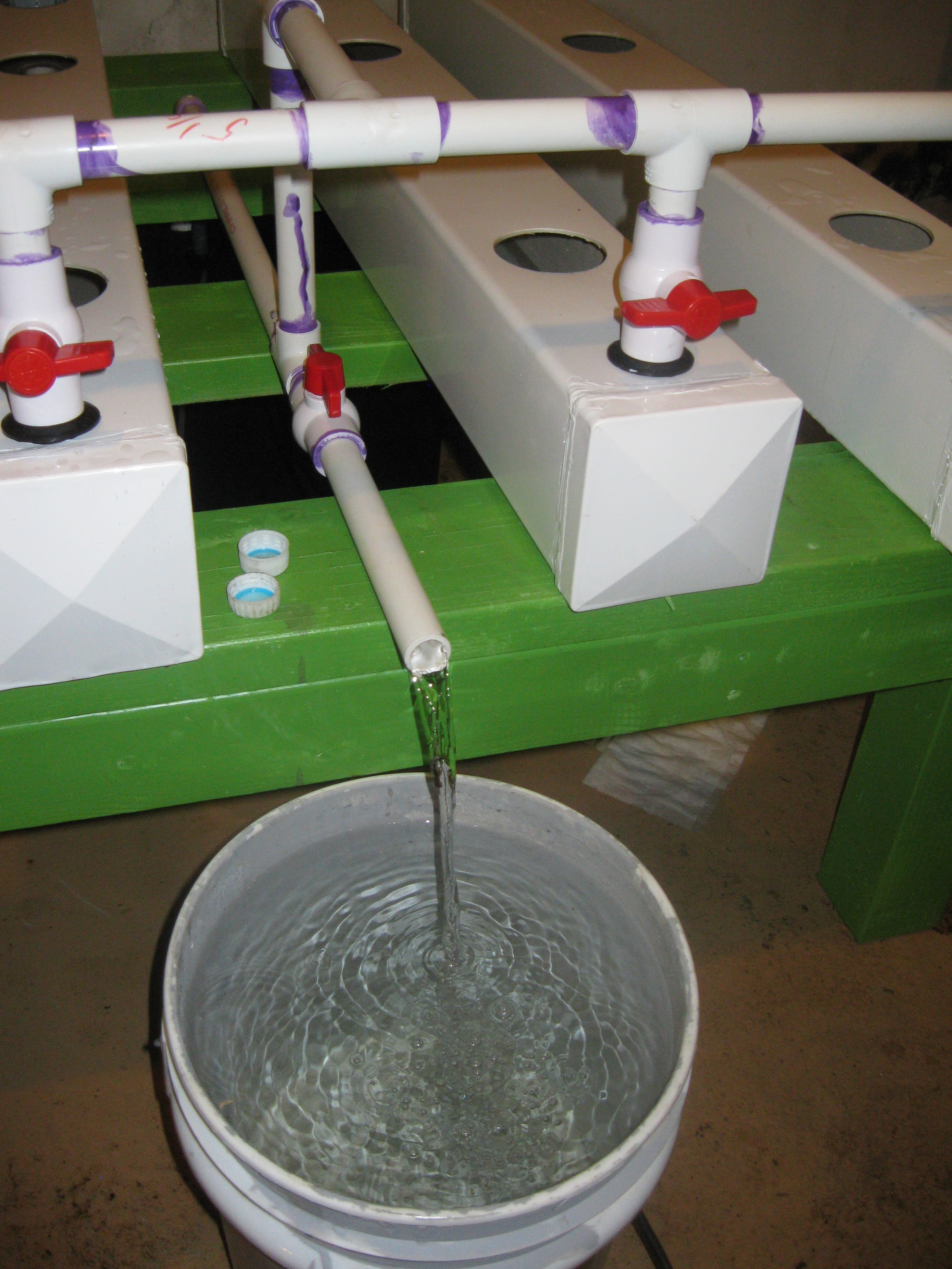
Additionally I wanted to test the reservoir pump out valve. This vale in the middle of the system is for using the reservoir's internal submersible pump as sort of a sump pump to drain out the reservoir into a bucket. The reason for this feature is for changing out water in the system if it get too dirty, the unit needs cleaning, etc for whatever reason you'd want to remove the water really. The whole idea is to make it easy and semi automated by using the same pump inside the reservoir and turning some valves. In order to use it the pump must be turned off, next the valves on each row need to be completely closed, finally the drain valve can be opened. The pump gets turned back on and pumps until the reservoir is empty.
Back to the topic of the pump being undersized. The mistake made with the pump choice comes down to a few things. Submersible pumps are rated in a height they can pump this is called the total dynamic head, this rating pertains to the vertical height the pump must move the fluid. The total dynamic head is also influenced by the design of the pipe fixture it is pumping into, in the case of the input manifold, also most total dynamic head ratings assume there is not fixture added. The trick is to design the pipe fixture or manifold in this case to fit within the range of the dynamic head of the pump. So basiclly I need to go back and take into account all the parameters of the manifold and make some calculations before getting a new pump. I plan on making a dedicated log explaining this a bit more clearly. Thats all for now, thanks for the continued support and stay tuned!
Discussions
Become a Hackaday.io Member
Create an account to leave a comment. Already have an account? Log In.