OUTLINE
After purchasing an electric 3 seater triple recliner from a UK company (DFS) the press and hold buttons to raise and lower the seat seemed rather old fashioned. It should at least be semi-automatic in that a tap of a button takes the seat to the next or previous pre-defined position. Having it controlled over HTTP would also mean that it could be controlled from any device capable of doing an HTTP GET request.
PROJECT GOAL
- Use a RaspberryPi to control the sofa movement.
- Use the current switches as inputs for the RaspberryPi.
- Create a RESTful API for control via other devices.
- Not to alter the sofa or remove the current functionaliy.
INITIAL TESTING
ELECTRONICS
It seems that most electric recling sofas and armchairs use a stanard 5 pin din plug between the control system and motor. I'm not sure if there is a standard or not but I believe it is just because the 5 pin din connector can handle high power throughput. This brings me onto the pinout.
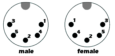
3. Live
5. Down button / Motor terminal 1
2. Up button / Motor terminal 2
Shield. Ground / Negative
The sofa requires 32V DC and uses in the region of 2A. All power travels via the switches directly to the motor. The switches are connected to one of two terminals on the motor and when open (not pressed) are connected to ground. When a button is pressed the live current is sent to the motor allowing the buttons to power the motor in either direction. This is easily controlled via a SPDT (single pole, double throw) relay which will allow for the motor to be connected to ground until one the relays is thrown to live. Each seat will require two relays so the sofa will require a total of 6 for movement. I have young neices so a 7th relay will also be used to turn the power off to the switches enabling a "parental mode".
I purchased a SainSmart 8 Channel DC 5V Relay Module which it turns out isn't made by SainSmart but can be purchased from 101 different companies on eBay for far lower prices. I chose this board for several reasons.
- Runs on 5V as does the RaspberryPi
- The 5v relay power and activation circuit are seperate meaning we do not need to push the 15-20mA from the GPIO pins to power the relays.
- Uses high current SPDT relays allowing 30VDC at 10A.
API
I chose to develop the API using Ruby. I hadn't previously used Ruby but as it is very easy to create RESTful API's using Sinatra and there's a great Pi GPIO library called PiPiper it seemed like a great choice. Ruby is well known as a language for creating RESTful API's on Linux.
CIRCUIT DESIGN
The circuitry can be broken down into two parts. The motors driver and the switch listening. The motor driver is very simple as I'm cheating and using a relay board which can plug into the RaspberryPi. The switch listening side is a bit more complex. As mentioned previously in its default configuration all power to the motors runs through the switches at 32V. The RaspberryPi GPIO header runs at 3.3V. I could use the 3.3V from the RaspberryPi and pass that through the switches but they have LEDs showing their active/pressed status which I wanted to keep. As the circuitry in the switchs is designed to accept 32V I need to make the voltage acceptable for the RaspberryPi.
Two possible options would be either using a voltage divider circuit to bring the voltage down to 3.3V or seperate them completly using optocouplers. If I had used a voltage divider and the powersupply spiked or one of the resistors blew the Pi would be toast. When the voltage can't be 100% trusted physical seperation is the way to go. The optocouplers I used come with two in a DIP package which is perfect as I need two per seat.
I used a great peice of software called Fritzing to design the breadboard. To the left side is the motor driver end which connects to the relay board. The right side is the switch sensing which takes the 32V from the sofa and sends the Pi 3.3V which it can work with.
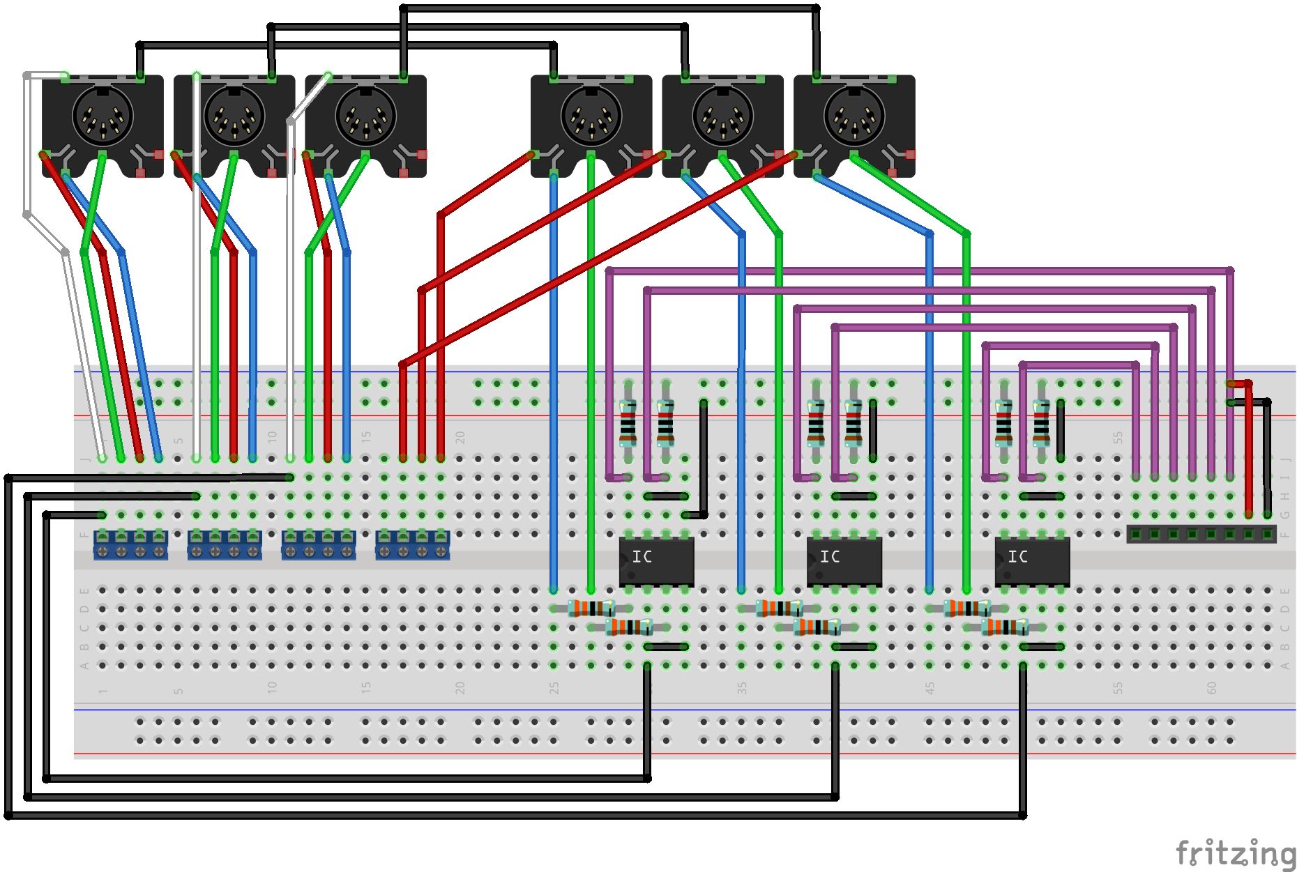
For some reason I wanted to use 5 pin DIN connectors on the circuit board to match the sofa connectors. This...
Read more »
 Nick Sayer
 Jared Young
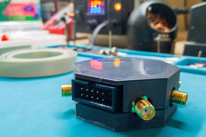
 Aditya Mukherjee
 bryan.lowder