 Tyler Ward (Scorpia)
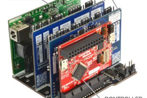
Erica is powered by five raspberry pi computers.
Two of these are used for controlling the eyes and performing computer vision on the video allowing Erica to recognise things like faces and QR codes.
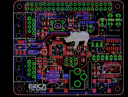
One controls the mechatronics inside the rhino, controlling the state of the LEDs and moving the ears.
The Brain pi controls Erica's reactions and moods which can change based on interactions with Erica and other factors such as the weather, it also has the input for the touch sensors.
The interface pi controls the networking between Erica and the outside world, it is equipped with a additional Ethernet connection and two wireless controllers to provide this connectivity
Two android tablets are also used to provide additional interactivity seeing Erica's current mood for example.


 Jon Buford
 Ashwin K Whitchurch
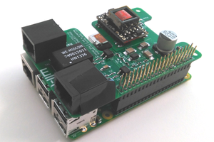
 Teemu Hakala
 Brieuc du Maugouër