 Stefan-Xp
Well, i considered to introduce the 7x5 LED Dot Matrix Display.
It's designed for maximal readability. With a character hight of 160mm, it is readable from across every room, even without glasses ;-)
In fact its just the Bare Arduino schematic with LEDs and a few transistors ;-) Its also used at the #Alarmierungsuhr.
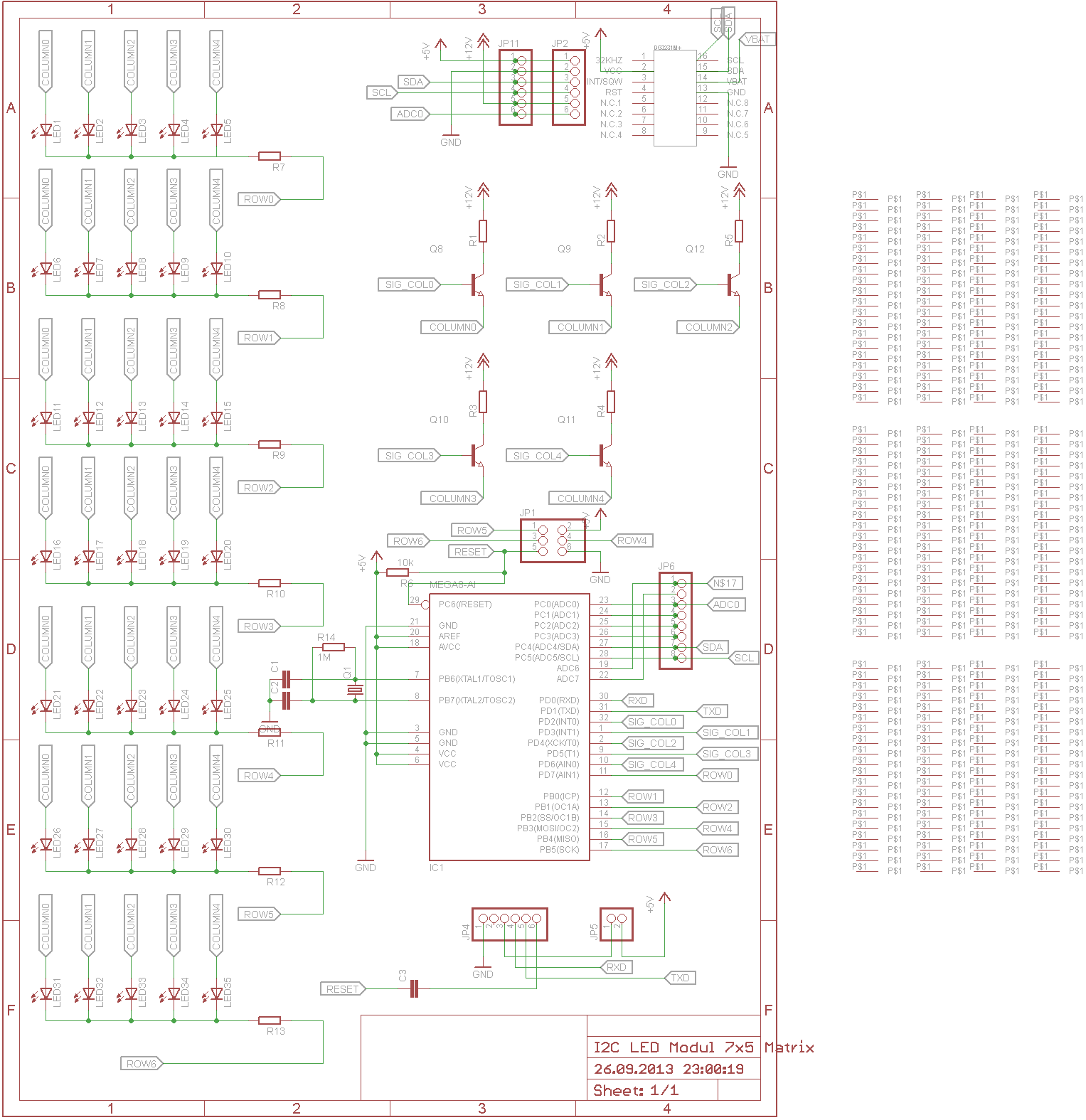
- Add a Resistor to the Columns, so different LEDs could be Used at the same board
- Add a current source for driving the LEDs instead of the Resistors.
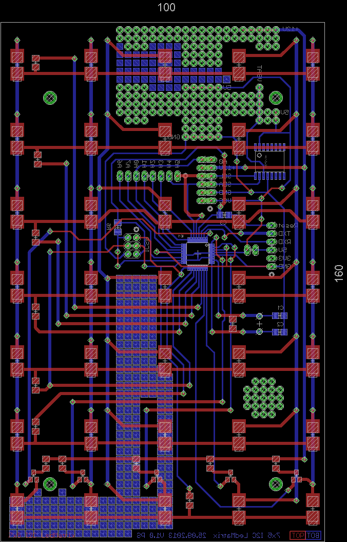
- Add a FT232RL Footprint for PC connecivity
- Use M3 Mounting Holes, M2,5 sucks :-/
- For other kinds of projects (Coffeetables etc.) IR-LEDs and IR-Diodes would be great ;-)
- Get Black or White Solderstop ... more expensive but should eliminate the green shine...
- Don't forget the base resistors for the Transistors
- Don't forget the caps for VCC :-/
Comments are as always appreciated ;)
Discussions
Become a Hackaday.io Member
Create an account to leave a comment. Already have an account? Log In.
gaaah... I meant M3 screws. Sorry. Why would I need that many and big LEDs for R8 :D nevermind - have I said I'm tired? http://www.mikrocontroller.net/articles/Transistor#PNP.2FNPN_als_Schalter.2C_wohin_mit_der_Last.3F complete link. I'm not sure that I've done the right thing either, with my controller board. There are so many wrong tutorials out there, that it's hard to tell what is correct. I've also never seen a 1MOhm resistor on the xtal inputs before. How do you connect multiple boards instead?
[edit] I thought I hit reply... Off to bed now!
Are you sure? yes | no
Well now it makes more sense ;) I Seen the 1MOhm on one circuit, not sure why i added it, most times it even isnt populated. I connected it via cables, therefore there is the 2x6 Pinhead.
Are you sure? yes | no
cool cool :) I keep asking myself if I know what I'm doing and I notice a lack of information on many aspects of electronics.. I will start with some basic stuff and experiments soon, while I will work on the other projects as well.
Are you sure? yes | no
Ahhh, LED displays, always fascinating! I'm fighting with my controller board for the three 5*6 stargate inspired displays. 2 shift registers will push the information through two ULN2803As so that 15 LEDs can light up in a row switched by a BC516, a pnp darlington transistor... because you don't want to put 150mA through an arduino and a 74hc595 ;) It took me a while to find out about the BC516. 3mm screws ftw! I just bought 1000 16mm LEDs for 11 euros through an ebay auction. I need a lot for my #R8-D8 - a distant relative of R2-D2 anyway :)
Is there a reason that your NPNs are connected like this? I've seen this link and am confused: http://www.mikrocontroller.net/Transistor
Can't you change the resistor R7 to R12 accordingly to the resistor needed for the color and then walk/scan through the columns? And I see a footprint for a DS3231! Is it good? I ordered two modules, one for the #fixietube clock and one for the stargate pad.
You could add some headers to chain them in each direction - for your coffee table ;) And where is a picture of it? I want to see this (board and log) updated ;)
This comment feels like a commercial for my stuff :( I'm too tired and wanted to start every sentence with "And then" or "And this" ...
Are you sure? yes | no
1000 16mm (Diameter?) LEDs? Are you serious? ;) What do they look like? Do you have a link?
My thougths regarding the NPNs were, that i wanted to use 12V, so i had to switch the "High Side". (Your Link does not work for me :()
Regarding the Resistors: This is true, as long as you don't wan't to have More than one LED switched on at a time. At the moment I'm a bit uncertain ;-)
The DS3231 is great, i like it, the only thing is, that my button cells seem emty. But i think you will also like them ;)
Soon I'm going to take some new pictures ;)
The problem with the headers is, that it is more difficult to join the PCBs in the right distance...
Are you sure? yes | no