Chris Slothouber
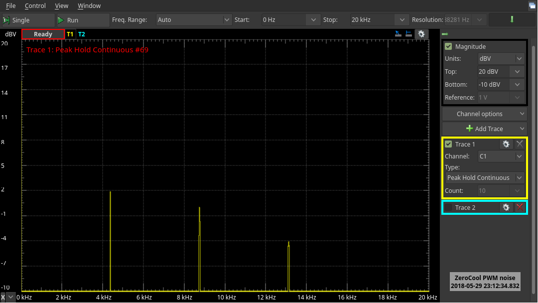
Similar Pi fan controllers use a software-based solution that runs on the Pi system itself and controls the fan via GPIO. This was a potential option, but was dismissed due to a few issues, including the added complexity (point of failure) of software running off-board. Opting for an always-on solution that doesn't depend on whether the attached SBC is running means losing access to the system thermal information. As such, our add-on board will need to measure the relative temperature itself, and make a decision based on this measurement to run the attached fan at an optimal speed. Given that noise (and MTBF) are a concern, this would ensure the fan only runs when it gets hot enough to affect CPU && wifi performance.
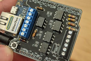
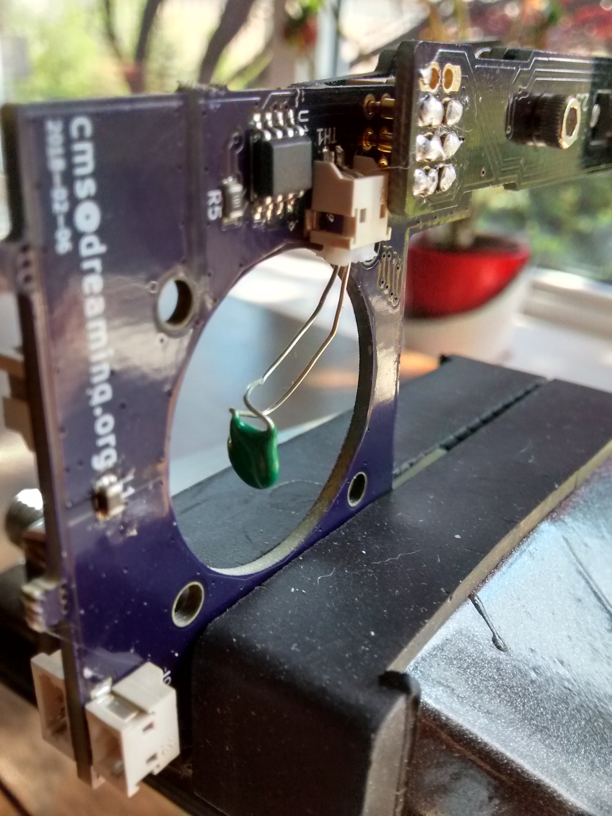
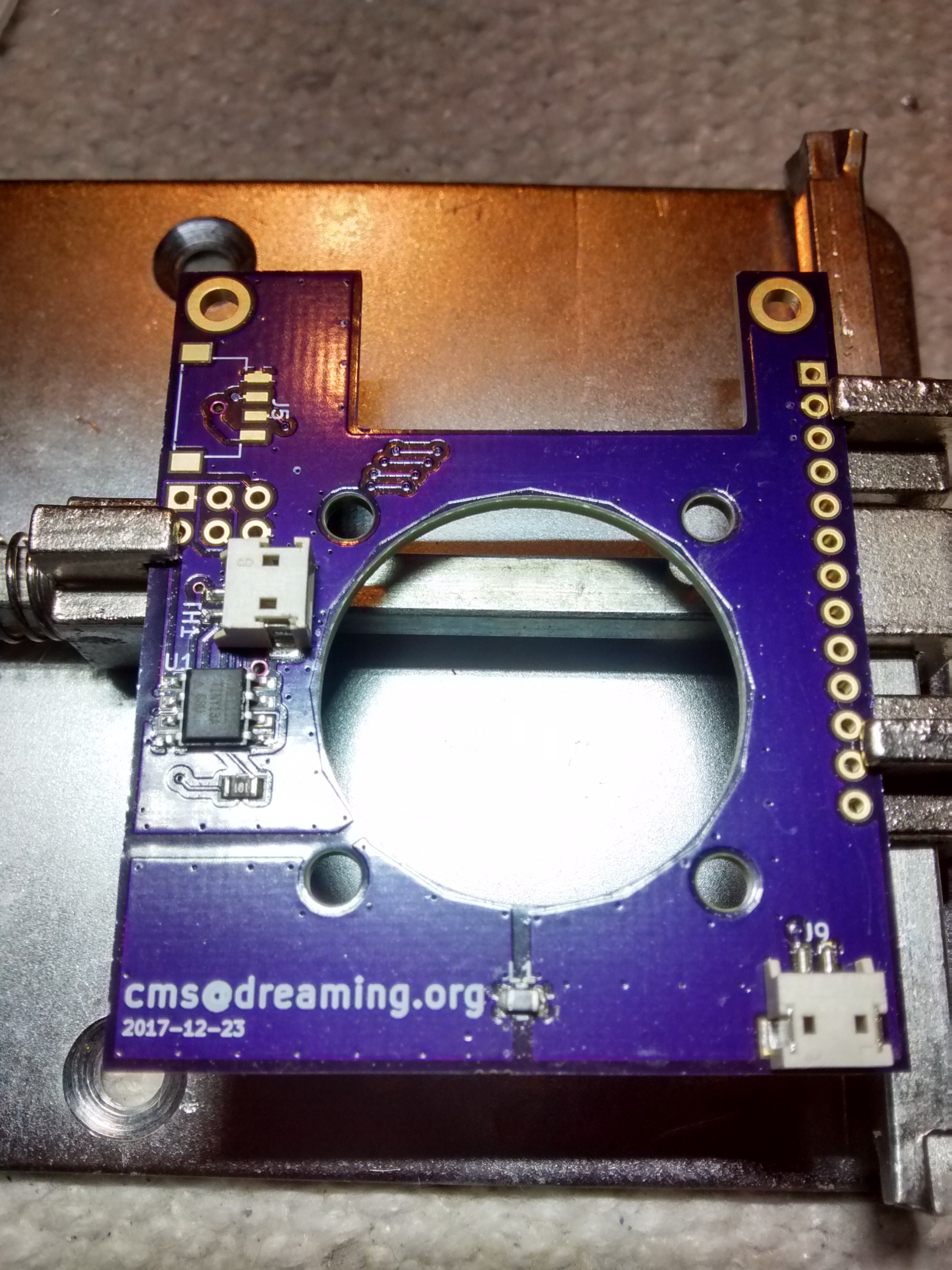
Due to the very compact nature of the Orange Pi Zero, few of the Allwinner H2+ peripherals are available with usable ports. This presented an additional opportunity in creating this add-on board, as any of these peripherals could be broken out from the included 13-pin header. In the end, I opted for the 2 additional USB ports, the (analog) video out, and the infrared RX.
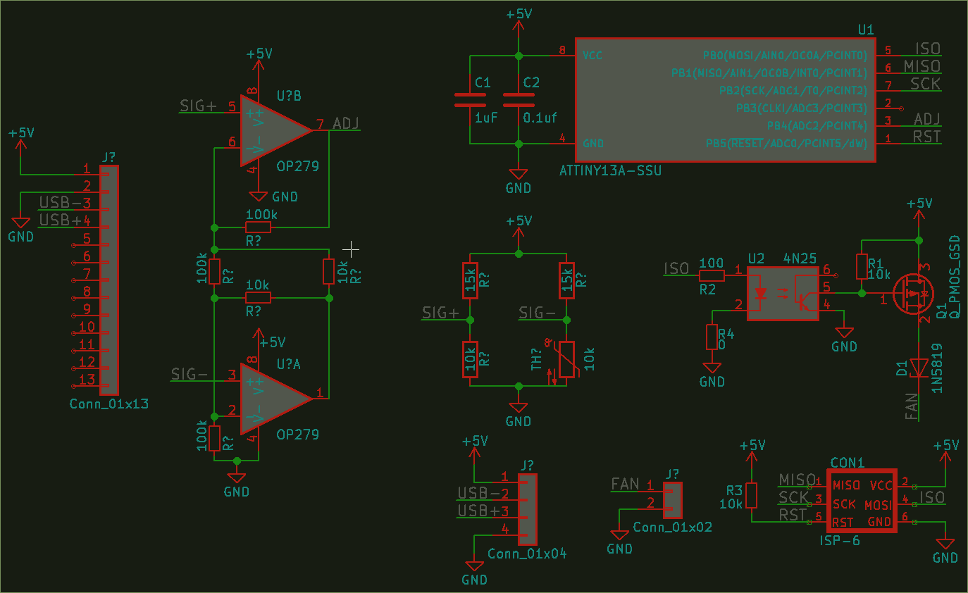
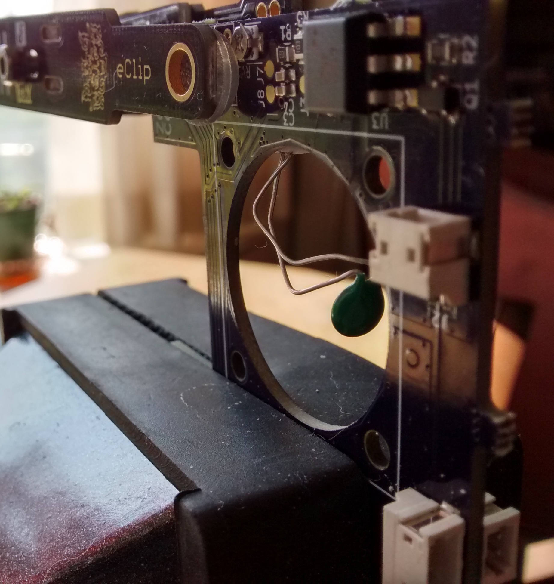
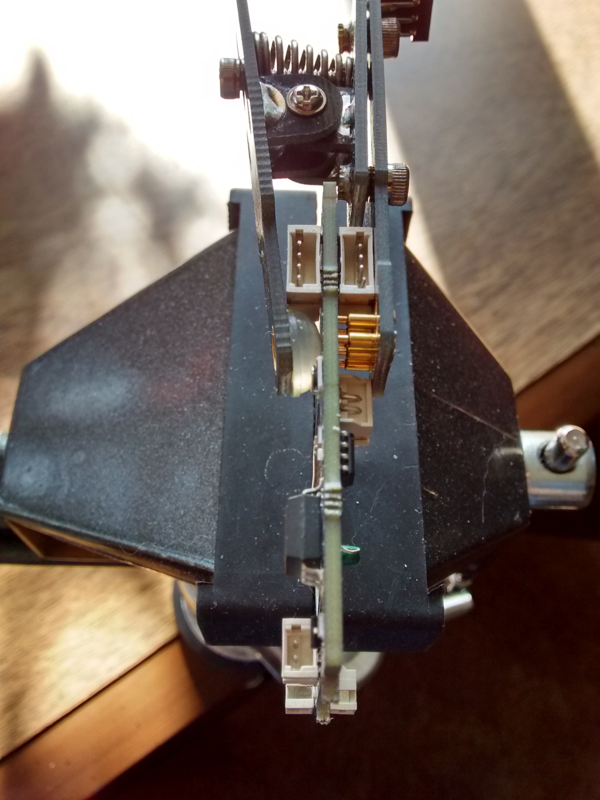
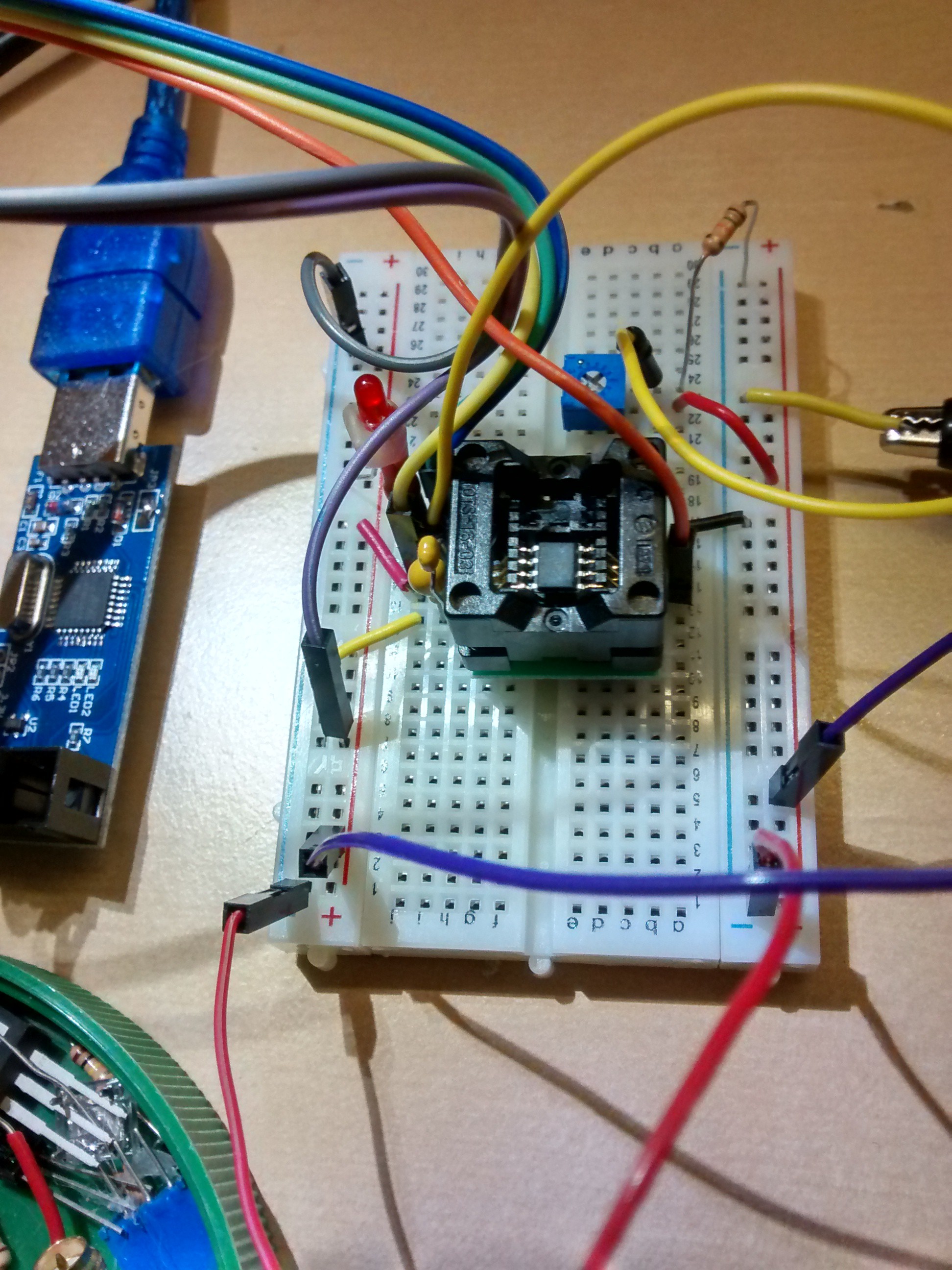
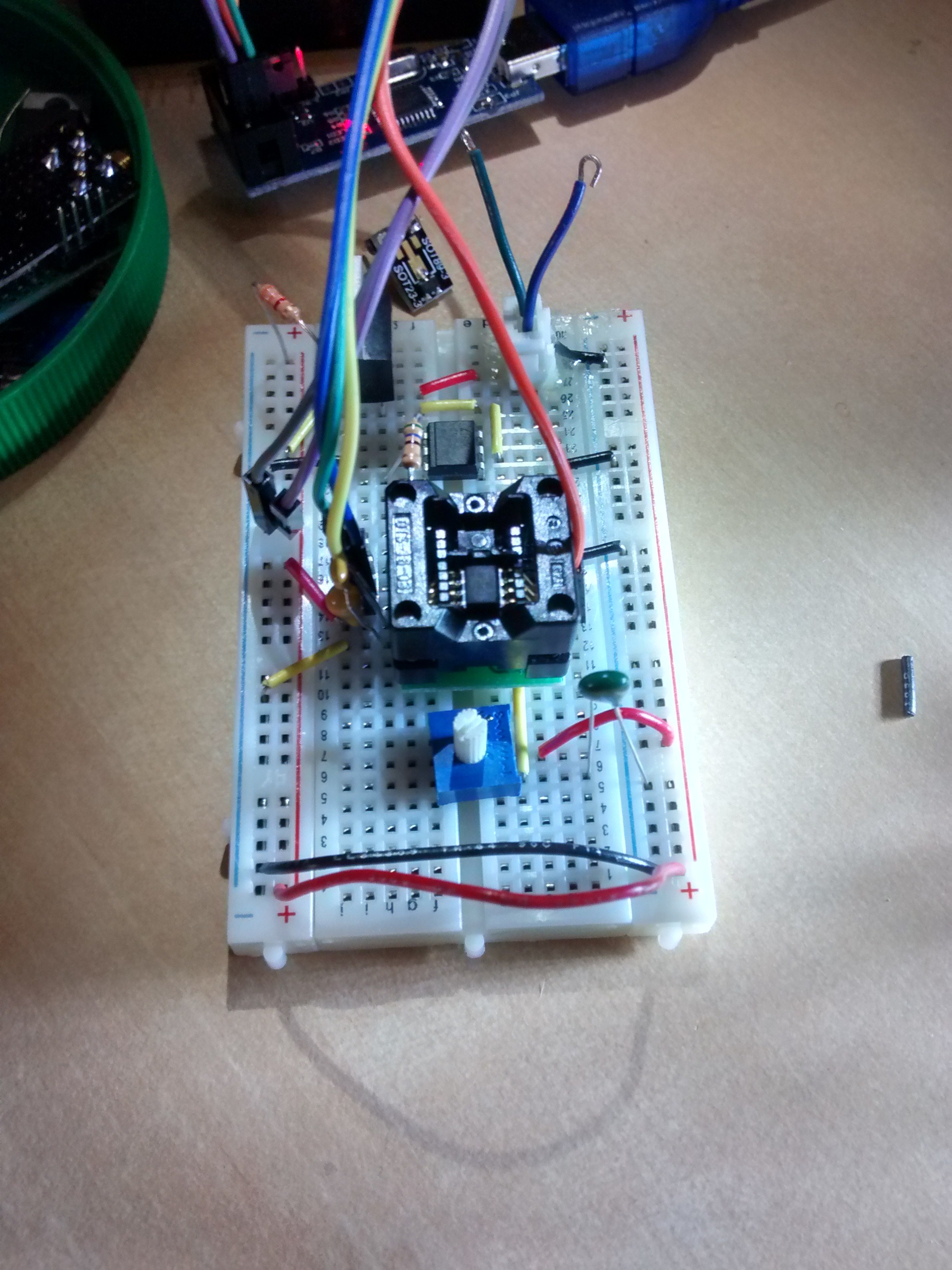
To control the fan speed based on temperature, a small microcontroller was selected based on cost and familiarity, along with an instrumentation amplifier and Wheatstone bridge with a radial NTC thermistor potted in a heat sink. The amp circuitry proved to be superfluous, as the MCU's ADC was able to acquire enough information in a simple voltage divider configuration in order to make a fan speed decision.


 robert
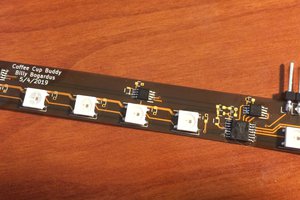
 Billy-Bogardus