 Chris Slothouber
When I set out to build this project, I knew I wanted to keep the design as simple as possible, while achieving
more with the expansion board than just running a fan. Using inexpensive materials already on hand kept costs low. Early on in testing the feasibility of this project, I used an ATtiny85 using the attiny core from David A. Mellis. However, with my assembled board now using the tiny85's smaller cousin, the tiny13, my code needed to change. While I could continue to use the Arduino functions provided by MCUdude's microcore, I wanted more granularity of control over the analog input and PWM output than Arduino can provide. With an external editor, I keep the Arduino IDE open solely for its time-saving programming facilities, resorting to the command line when necessary.
Locating some code from a blogger from Leeds, UK, I was able to modify his PWM LED program to sample my thermistor bridge and output a fan speed appropriate to the temperature level. While I had already tested
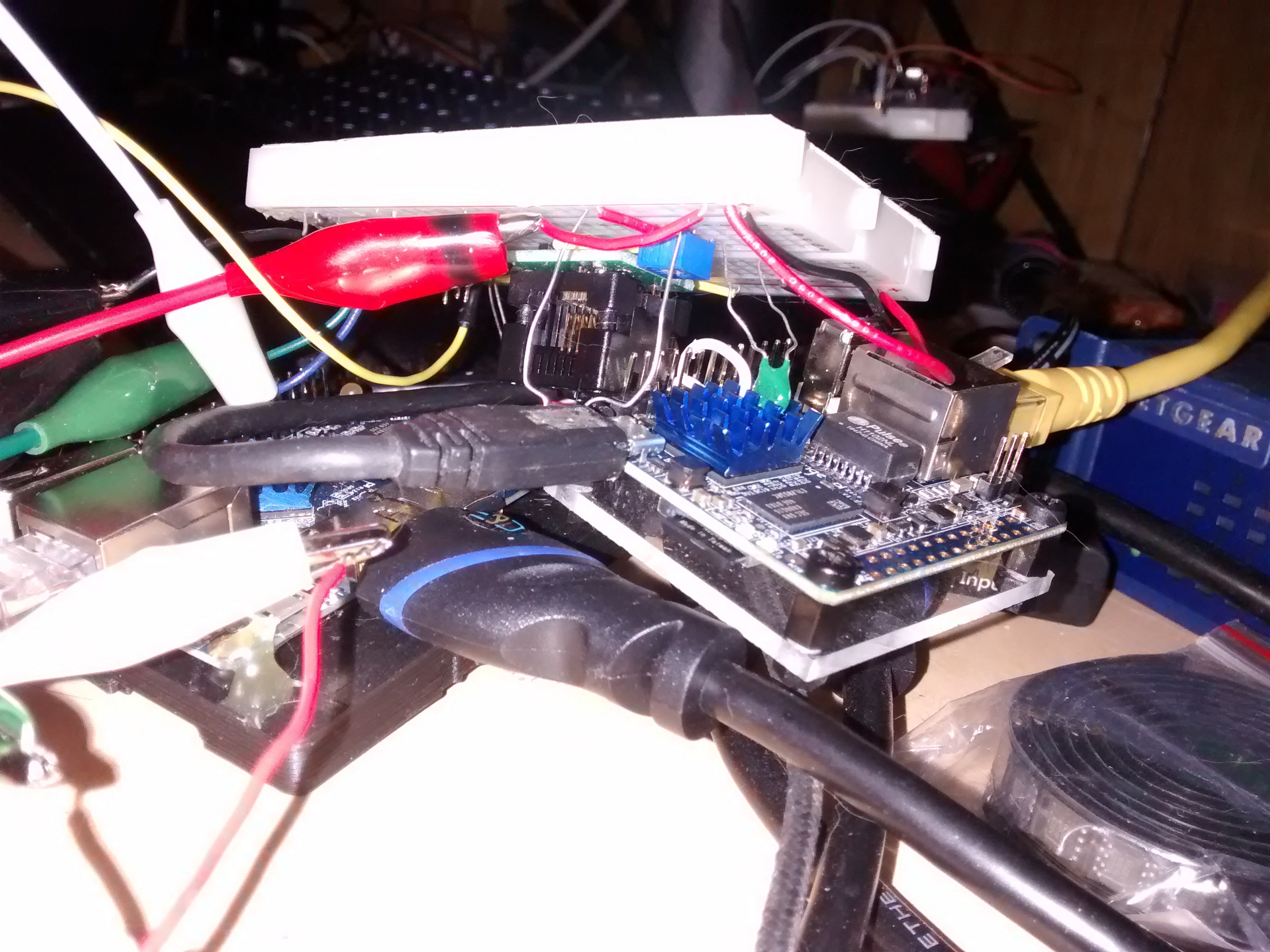
the feasibility using of controlling fan speed with Arduino's analogWrite functions, I modified adnbr's code to read PB4/ADC2, match the reading to a frequency corresponding to a particular fan speed, and output this value on PB0/OC0A, which switches an opto-isolator and a MOSFET to control a cooling fan. Having assembled a perfboard with a tiny85 for long-term testing with another SBC, I know this design works reasonably well.
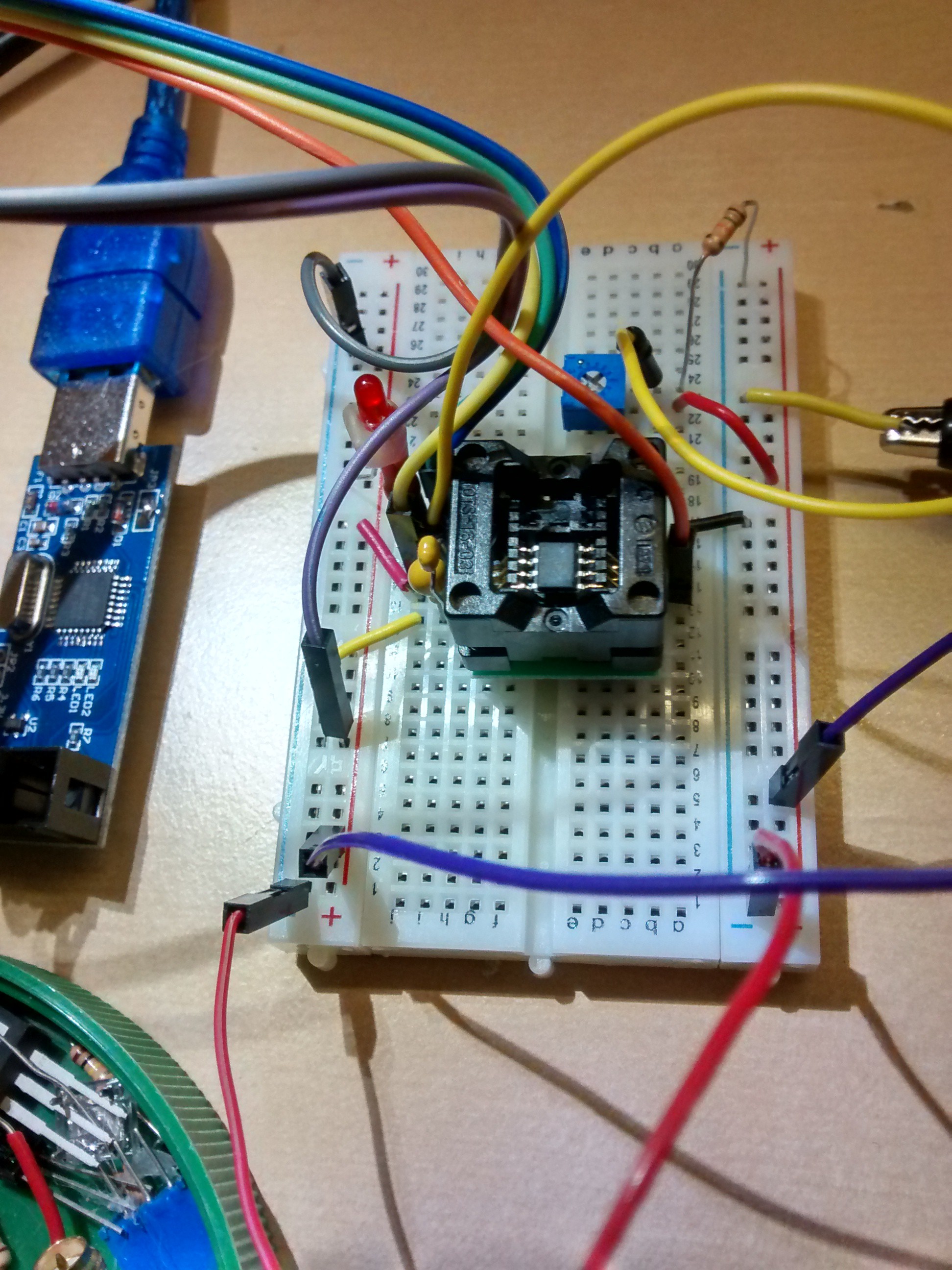
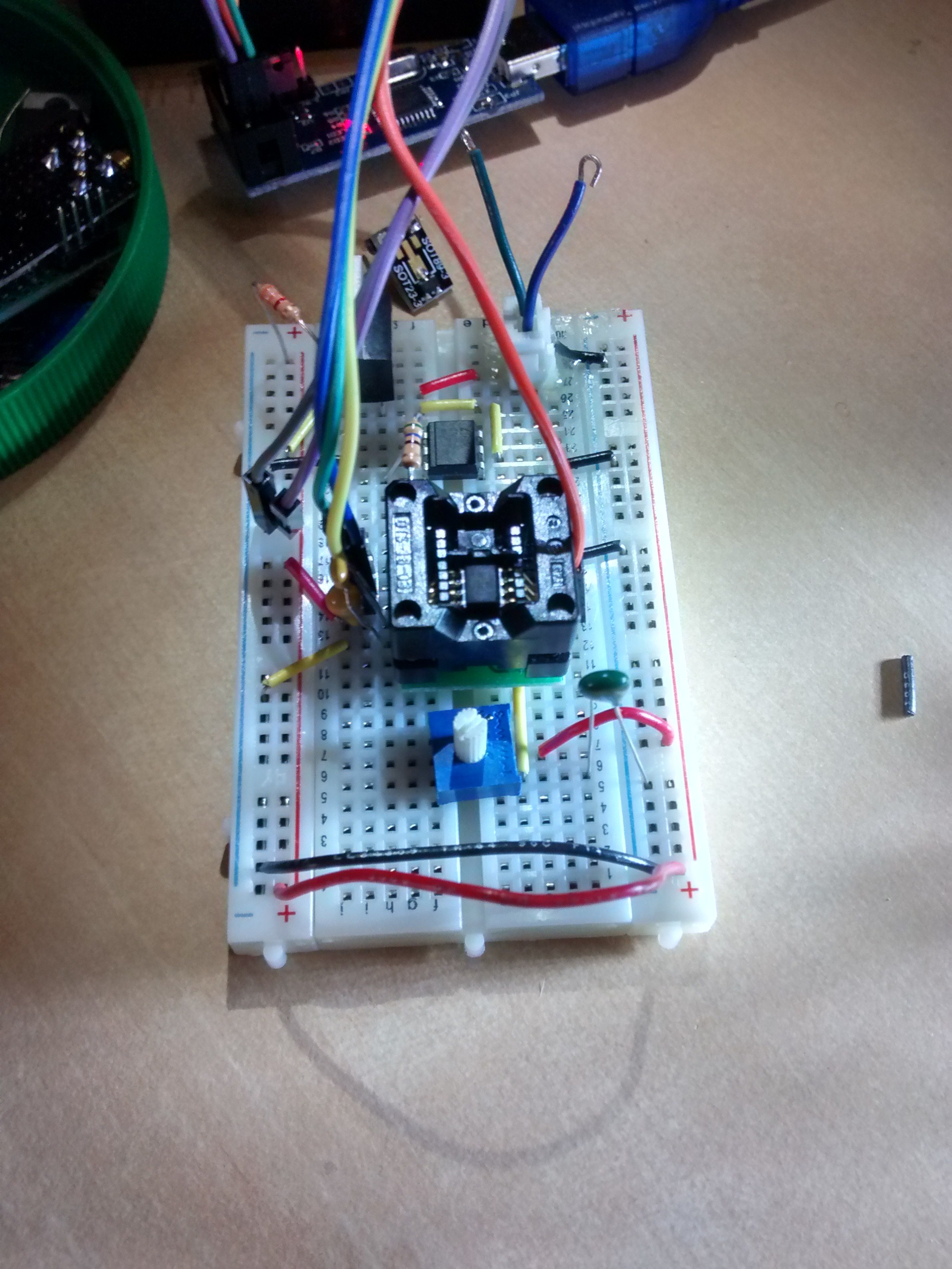
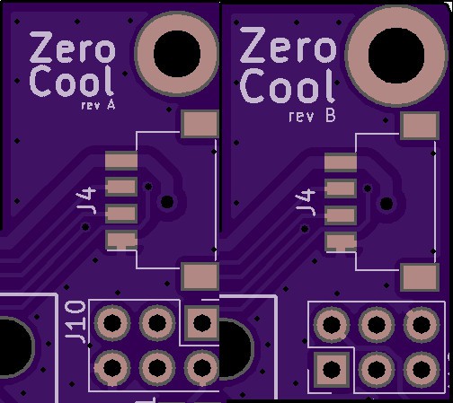
After assembling the board, I discovered an error made during the schematic and board layout stage of my
workflow. Specifically, I had swapped around the drain and source pins. D'oh! No wonder the fan was getting full VCC no matter what adjustments I made to the resistive bridge using the trimpot. While the MCU samples the bridge and outputs the correct equivalent pulsed voltage to the 4N25, the first revision of my board design has effectively bypassed the FDN340P, supplying the fan with full voltage at all times. Before making the appropriate changes to my schematic and board layout, I breadboarded the entire circuit again, this time using the ATtiny13 micro controller, and the FDN340P p-channel MOSFET. This allowed me to further test my code with nearly the same components as my board uses.
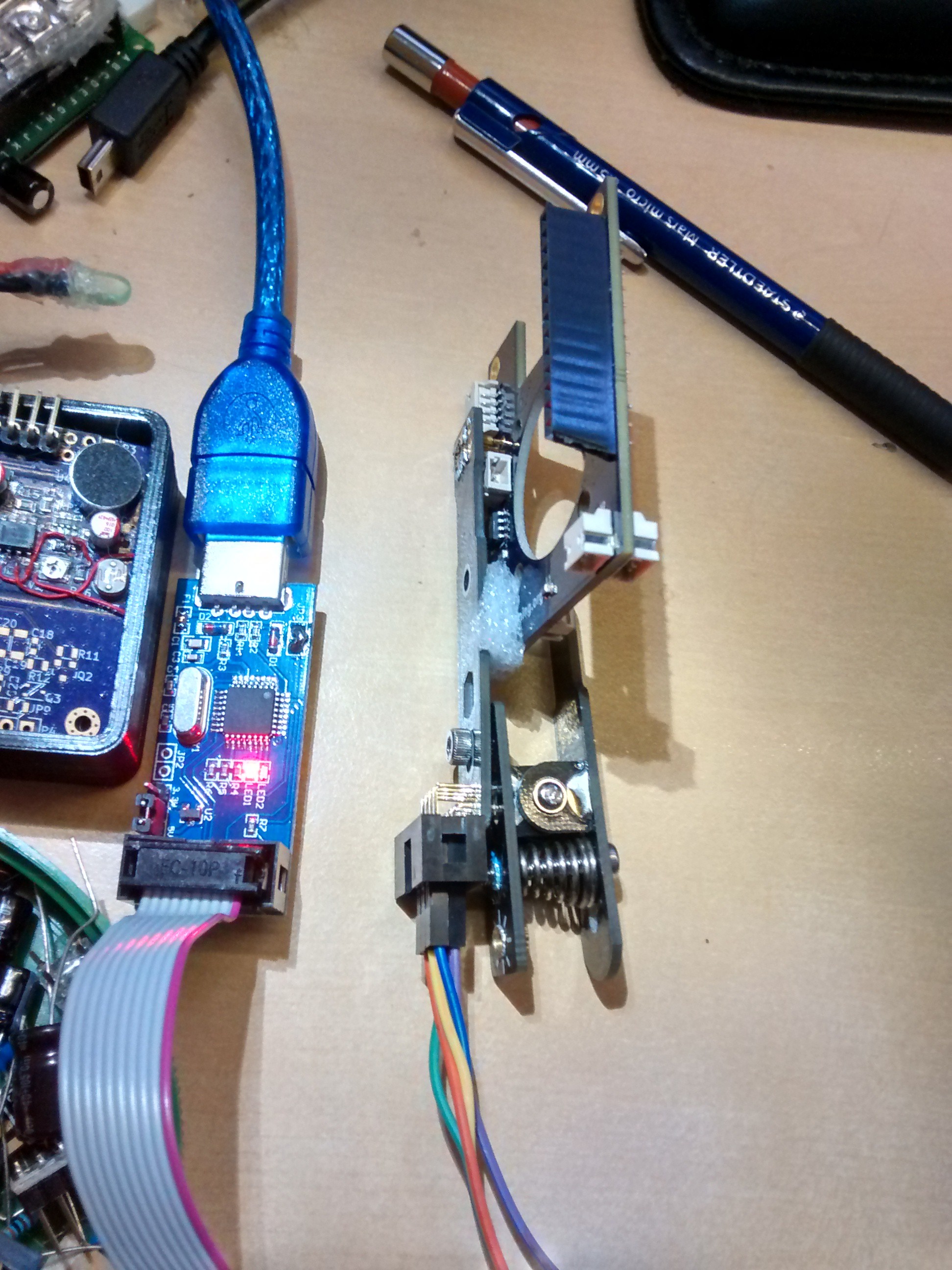
With the required change to the MOSFET pinout, I took the opportunity to also modify the mounting holes and round off the corners a bit. Given that my programmer is a recent addition to my arsenal, I also modified the 6-pin ICSP header's orientation so that the clip can better achieve a better fit.
Discussions
Become a Hackaday.io Member
Create an account to leave a comment. Already have an account? Log In.