 Kostas Lagogiannis
The project's drive is to empower people by allowing them to have access to energy through a community driven project and a low-cost design.
To this aim, this project's will explore the potential of building a low-cost alternator out of industrial plastic. This alternator should be tuned towards a wind-turbine application. The main aim is to design a turbine that can be manufactured out of cutting plastic-sheets, easily assembled and low-cost (<250 euros) so anyone can laser-cnc cut his own. Our design philosophy is to minimize the diversity of materials and constuction techniques as much as possible to reduce the cost of harvesting aeolic energy at this micro-scale. Thus, there may be various efficient turbine designs out there, as for example the 3 blade horizontal axis turbine, but implementing such designs with our means may reduce the cost/output ratio. We therefore seek to optimize the use of our plastic-sheet cutting process for the construction of a working wind-turbine + generator.
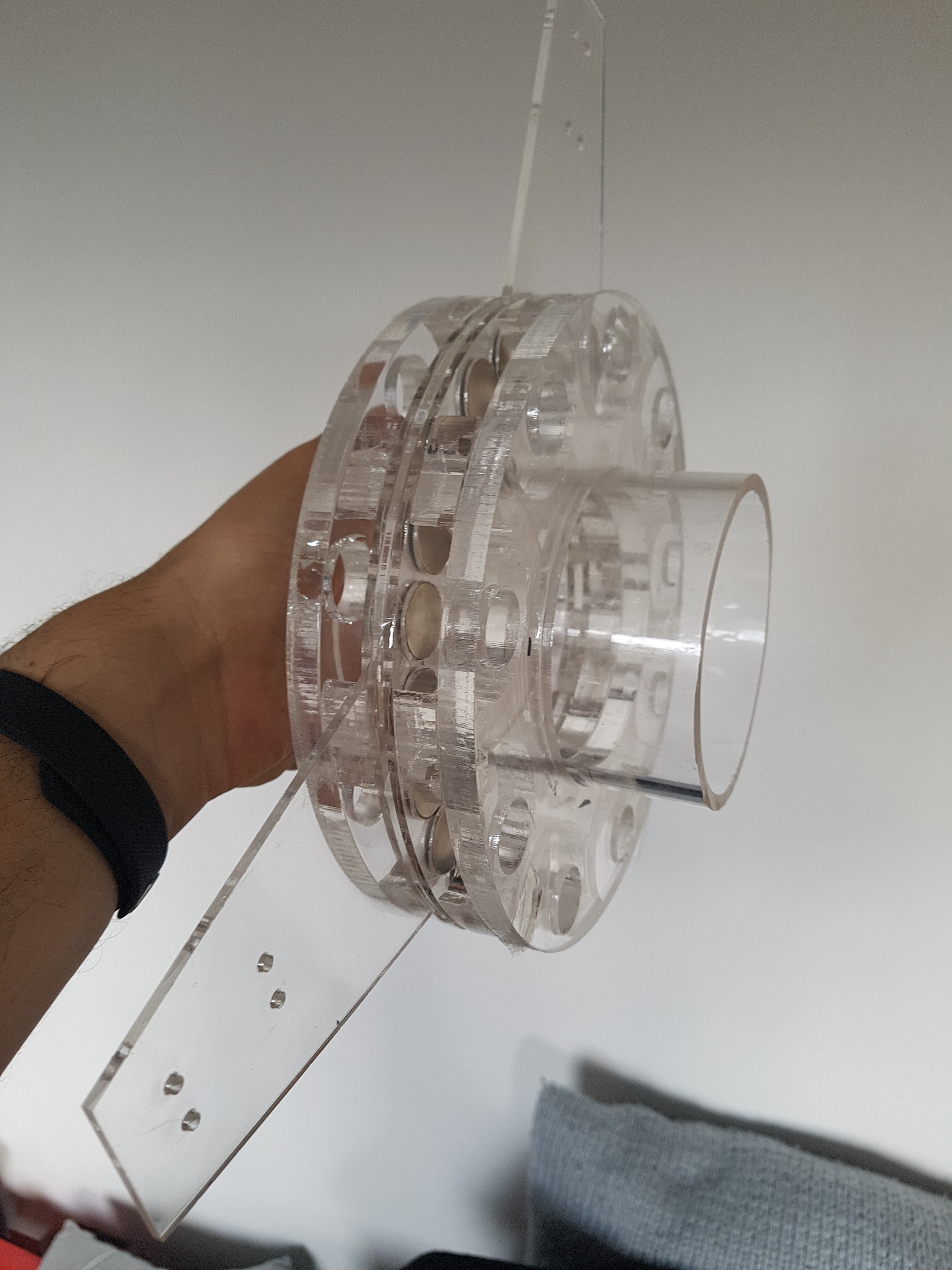
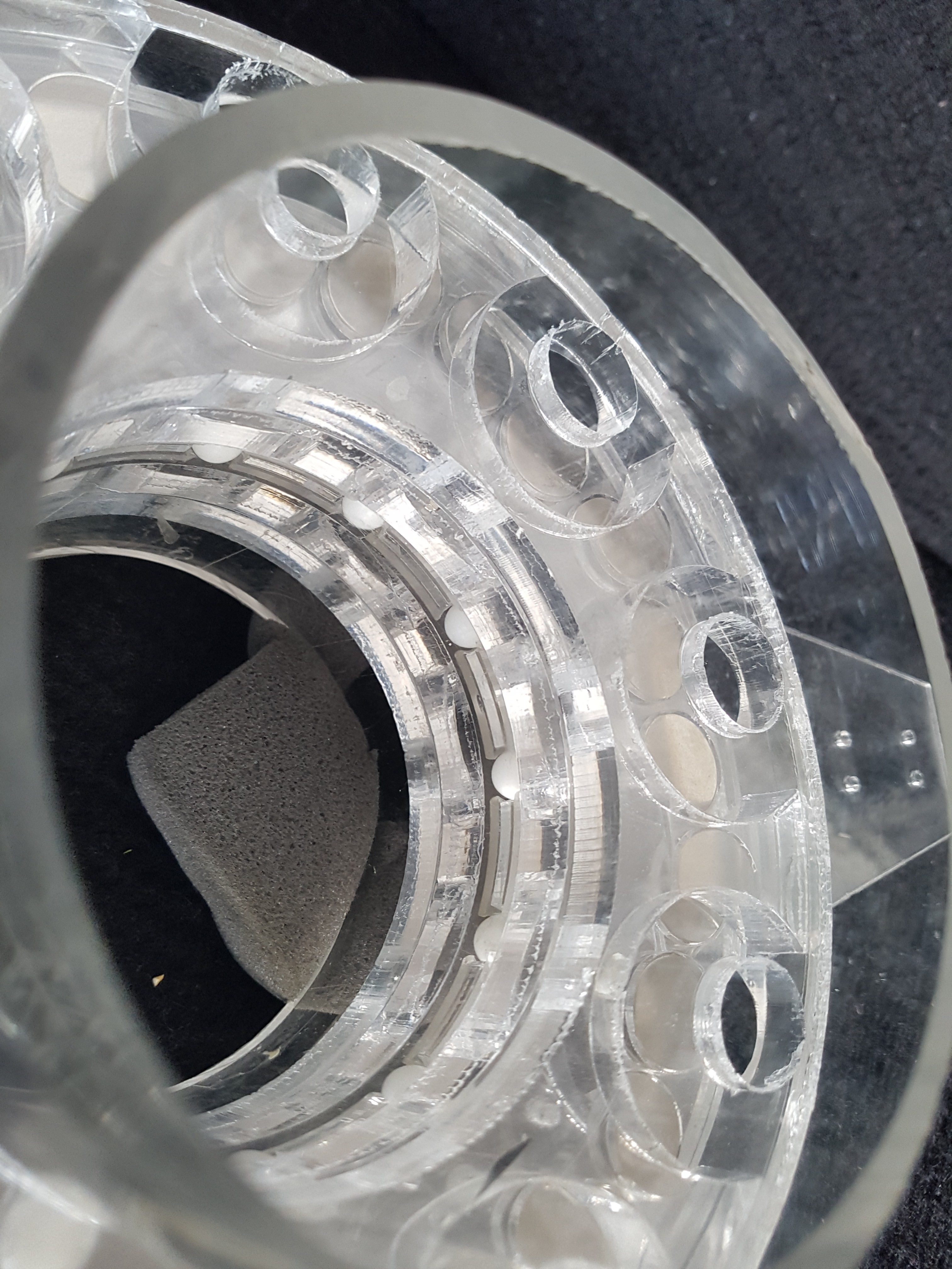
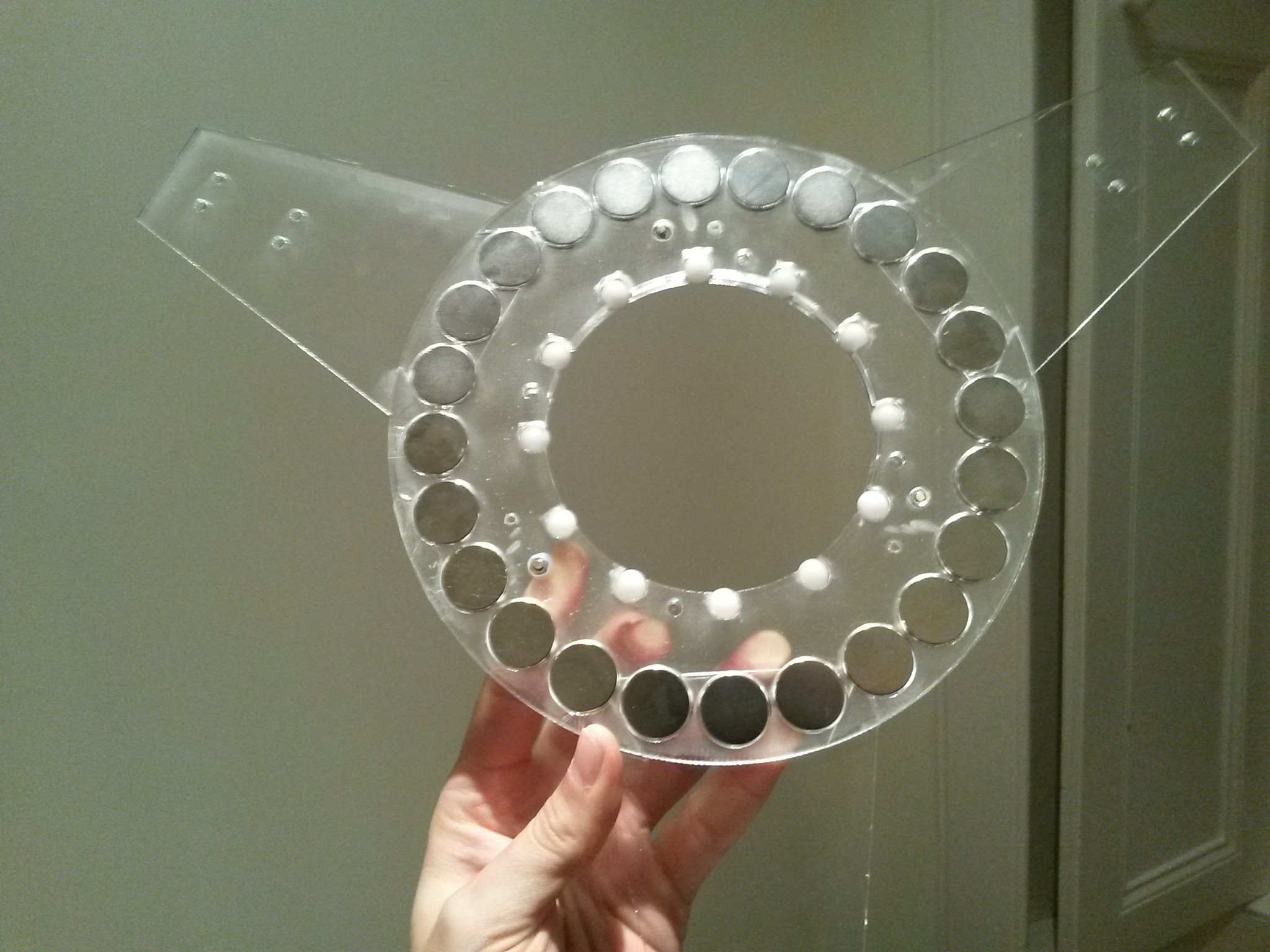
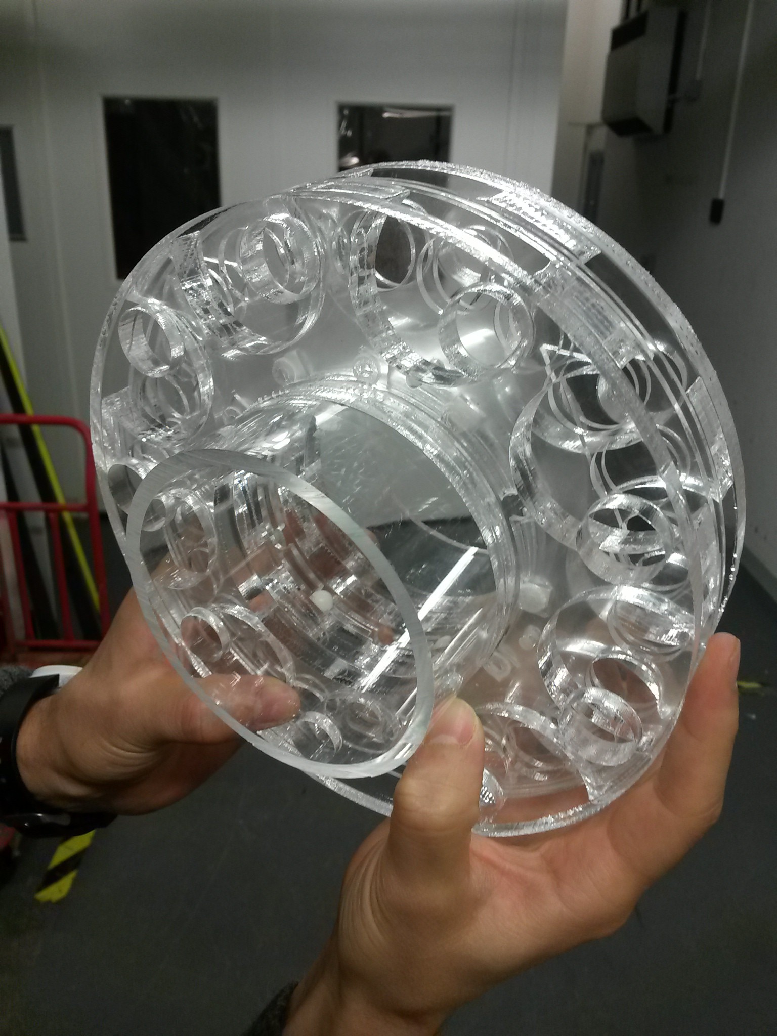
The pictures shown are of a 3D rendering of our design of a single rotor and dual-stator (3-phase 9-coils each), made out of acrylic plastic (perspex). The diameter of the design is such so the parts can be cut-out of A3 sheets (20cm diameter of rotor and stator). This particular size makes the design suitable for constructing with the abanduntly available CNC or laser cutters of A3 size. Our design aim is to achieve simplicity in construction & assembly, beauty and an acceptable efficiency (output/cost) ratio. We would like to achieve 400W at moderate wind speeds , but such output will depend on the turbine design as much as the alternator (more on the design spec will follow).
Further, due to the nature of this open-design project we aspire that this project will generate community driven revisions to improve the initial design.
At this stage we are building a prototype out of acrylic. Although acrylic is low cost and has low creep and water absorption, it cannot sustain temperatures beyond 80 celsius, and its quite fragile. Thus acrylic is used here only for prototype, and stronger plastic would probably make it into the final design.
The project is shared under a Attribution-ShareAlike 4.0 International license


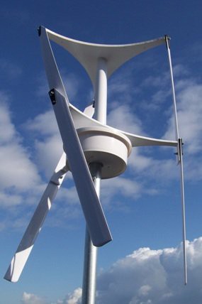 The picture from a Darius flat-blade turbine designed by Chad Maglaque called the Jellyfish. Such a design could allow a modular expansion of the turbine.
 Matt Reimer
 Supercell
 Greg
Greg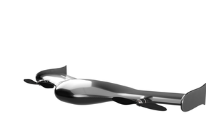
 Naman Pushp