 charliex
The basic idea is to have RGB LED strips that are controllable via TCP/IP from a master host and avoid things like DMX512.
I picked up a bunch of RGB WS2812 strips from china, and a DMX512 USB adapter with a controller to run RGB strips, just to see how it worked. It was terrible, even for a wired connection, DMX itself is a really poor protocol and it was super slow pushing it all the data to the strips.
It does support the other types of LED strips too, 400/800khz and 2811/2812 it's based upon the component in this project
Also here is a link to Mark Hastings original project (way back in 2011)
http://www.cypress.com/?rID=57336
So i started to look for alternatives, I looked at all the various CPU options to drive the chips, lots of people complained about timing issues, or tight loops and so on and I wanted to keep costs per node down a bit, so initially i figured use an STM32 and just throw MHZ at the issue, that way i could run effects and stream in.
Then I picked up the nRF+ chips everyone uses and figured i'd build up nodes of those with controllers/repeaters etc. Just as I'd ordered them Hackaday showed the ESP8266 off, so immediately I ordered a box of them.
Just before Hackaday's 10th anniversary, I was looking for ARM chips that were cheap, and digikey had an offer on some at $1 so i bought all of their stock, but then I saw the $4 Cypress PSOC http://www.cypress.com/?rID=92146 , i have loads of dev boards, so i grabbed 10 of them to add to my infamous drawer, which is now about 4 sets of drawers by now.
After poking around with it , I then found a project by a Cypress Engineer who'd implemented the WS2811 protocol as a component on the PSOC5 , I grabbed one of the new boards and the code and started to make a few small changes, then it complained about not enough UDBs, after looking I saw that there are two versions of that dev board, the 41 and 42 , the 41 has no UDBs the 42 does, and of course i'd just ordered the 41's. So I bought a bunch of the chips (since that is the only change ) and new dev boards, but then I ended up giving away most of the 41's to people at the HAD event.
So once i had the 42 variant, wired it up, added a few routines and let the wifi have hers with a strip , so she could code up her own routines.
The Cypress version only supports RGB, RGB is not suited for fancy colour effects , fading and tweening etc. Most colour models are fairly math intensive on the conversions, so i opted to use HSV/HSL which isn't as good as say Lab CIE but works just fine when you are crossfading colours and so on. Which gave me this
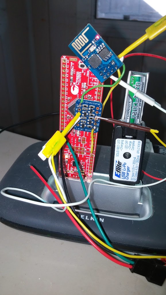
So next was adding the WIFI version, I wired up the ESP8288 added the bi directional level converters on the RX/TX/CH_PD lines, and a LD1117-3.3v , that is what i had at hand.
In cypress creator i added a second UART, configured it for 115kbps 8n1 and wrote a simple echo to the main UART back to the host, loaded up a serial terminal software and tested the chip, I forgot the CH 3.3v tie up the first time, so added that and the chip booted up, once i'd figured out that the chip wants all caps with \r I added it to our wifi network and pinged it, worked. Then i found out it remembers that setting after a reboot, something i'd hadn't known about before.
Next I setup a UDP listening cip and wrote a simple app to send out 450 bytes of data (150 leds 8 bits per RGB. so 150*3) and it worked, so far so good. I had the Frankenstein's monster version of the board.
Then I immediately decided to make a PCB in Eagle and cut it out, for some reason.
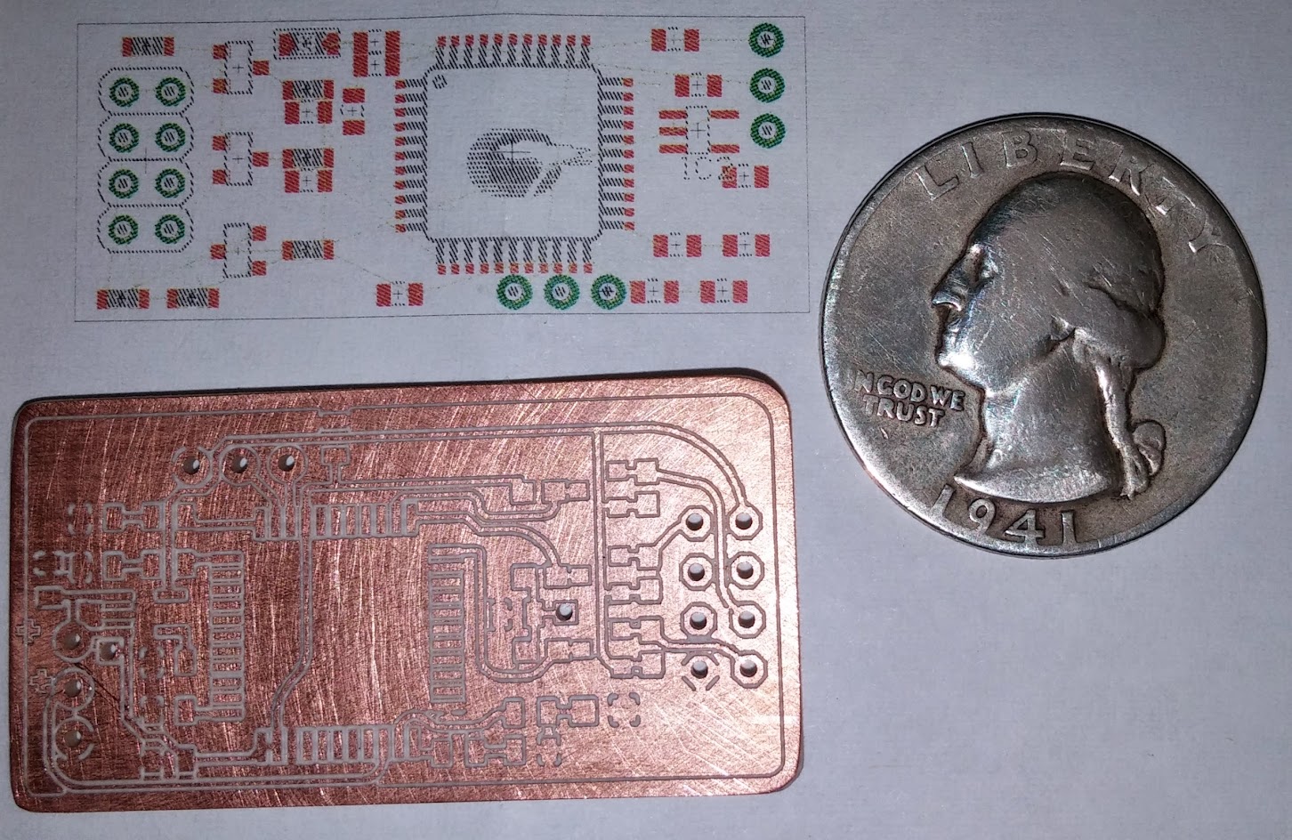
That is pretty much all i'd need (at the moment ) so after that was laid out, i decided that i should probably remove the clip on jumpers and just solder in permanent wires instead, just in case it got knocked over or a fly flew past and they popped off.
So i took off the jumpers, soldered in the wires and then booted it up, nothing, nada zilch zero.. checked the wiring, stated to question the rx<>tx tx<>rx or rx<>rx tx<>tx etc. Watched the data coming out the scope, then disappearing when i added tx from chip. After an hour or so i changed out the ESP8266 thinking maybe i'd damaged the rx/tx lines, i could still ping the device from another PC, so some of it was working.
Same result, so checked everything else, seemed to be OK , after another hour i figured lets just build a second board.
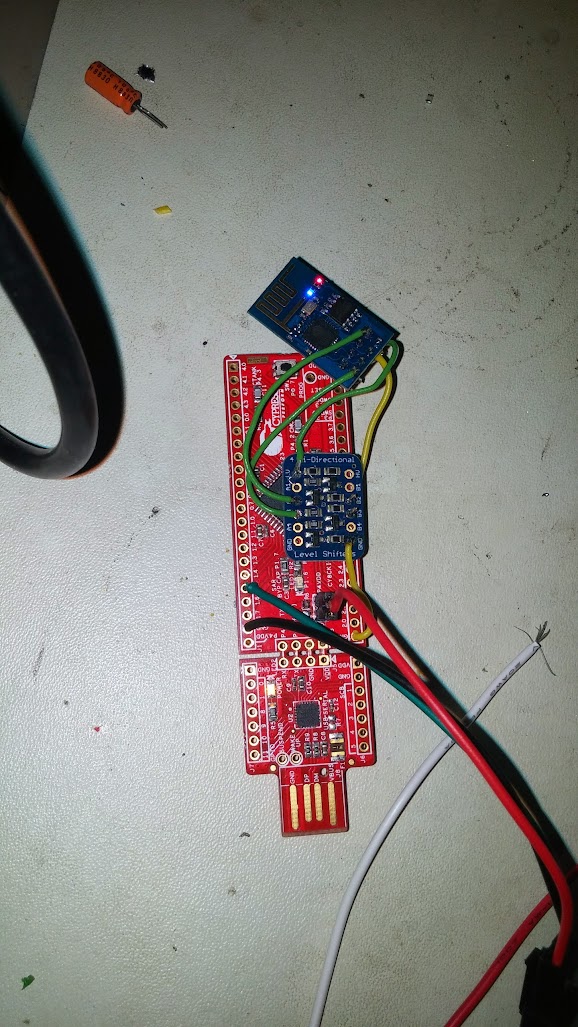
That one came out neater, the LD1117 is on the back. And it worked first time, so that allowed me to go back and keep working on the software, parsing the +IPD return packet etc.
I then back ported all the code from the PSOC for running the effects to desktop C and made a test app that could basically run the same code, that'd give me an idea of the speed difference.
I figured out I could send out 450 bytes of data at 35-40ms intervals without the data being buffered/lagged. Not great, but a good start.
That gave me this, the speed isn't too bad and you do see stutters from time to time as the latency of the connection increases, but overall its working pretty good.
Next step is to improve the speed, i'm using the original firmware of the ESP8266 so i'm sure i can improve it, but it is getting there.