Close
0%
0%

Getyoo Clickey NFC tag reverse engineering

The Getyoo Clickey contains some interesting hardware: a STM32F102C8 microcontroller and a NXP PN512 NFC transceiver

Similar projects worth following
The project goal is documenting my reverse engineering work about my Getyoo Clickey.

Intro: the Getyoo clickey is a smart call-card exchanging stuff designed for conferences.
It has an USB slave interface where you can upload your contact information. During the conference you can exchange your contact with other Clickeys. After the day you can download the collected contact informations.

Here is what I know from the device:
- MCU: STM32F102C8
- NFC transceiver: NXP PN512 (http://www.nxp.com/documents/data_sheet/PN512.pdf)
- It shows up as a mass storage device (http://www.st.com/st-web-ui/static/active/en/resource/technical/document/datasheet/CD00210831.pdf)
- VID:PID: c251:1c03 Keil Software, Inc.
- lsusb verbose output: https://db.tt/NPams7kk
The lsusb information reveals that the firmware is built using the KEIL tools.
It might hava a bootloading capability, I will look around the KEIL application notes around the USB mass storage devices and bootloaders category.
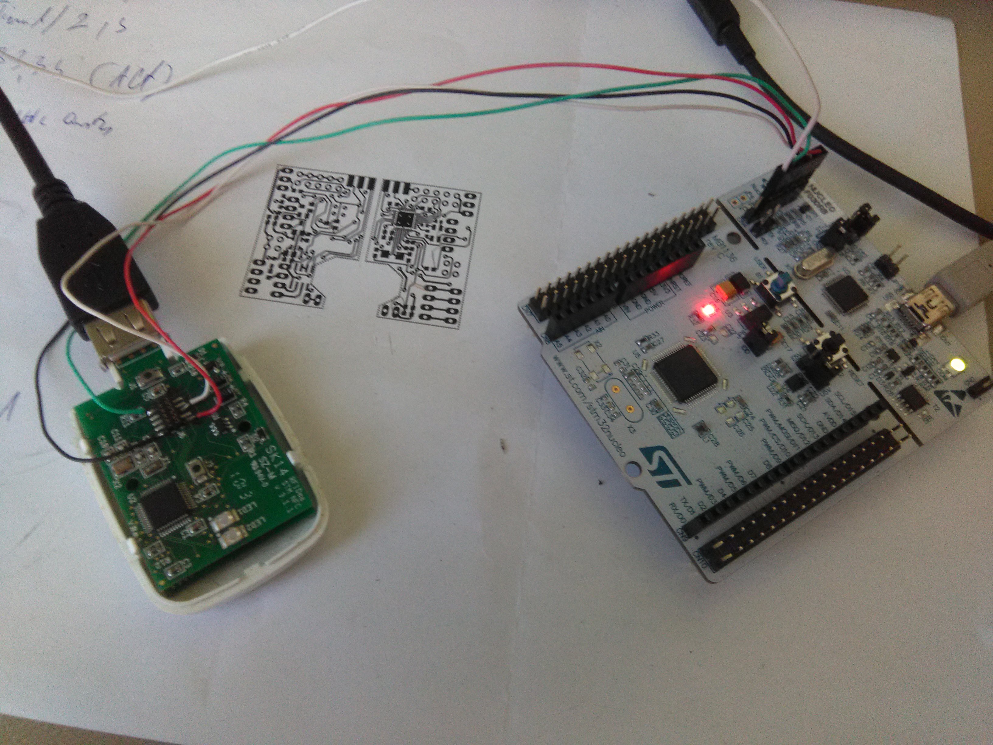
Hardware info:

The device is made from two PCBs. A CR2450 battery is placed between them.

MCU board

This is a 2 layer PCB with the following markings:

  • SK14
  • SZ-M
  • RFIdea STM NFC v 3.1.1

Components:

  • STM32
  • 2 LEDS:
    • LED1 (red): connected to PB13 through a 100 Ohm resistor
    • LED2 (green): connected to PB14 through a 100 Ohm resistor
  • some passive components
  • a clock oscillator connected to the PC14-PC15
  • a 12 MHz oscillator connected to PD0 (OSC_IN)
  • J1 switch is a reset switch (pulls the nRST pin to GND) this button is hidden from the user but it could be accessed through a hole.
  • J3: (contact exchange button): pulling to VDD connected to PB10
  • J6: JTAG connector. Pinout (1 and 10 pins next to the J6 text on the silkscreen)
    1: VCC
    2:
    3: PA14 JTCK
    4: PA15 JTDI
    5: PB3 JTDO
    6: PA13 JTMS
    7: PB4 nJTRST
    8:
    9:
    10: GND

RF board

This is a least three layer PCB (have one inner ground plane under the RF area) includes the follwing markings:

  • SK14
  • SZ-2D
  • NFC by RFIDea v 3.1.1

The PCB populated with the PN512, a 27.12MHz oscillator, the interboard connector, and a bunch of passive components.

Interconnect connector pinout (see pin1 marking on the photo).

1: PN512 D7 (UART mode TX) - SMT32 PA3 (USART2 RX)
2: PN512 D6 - NC
3: PN512 ALE (UART mode RX) - STM32 PA2 (USART2 TX)
4: PN512 TVDD, SVDD, AVDD - STM32 VDD
5: PN512 VBAT - STM32 VBAT
6: PN512 A0 - GND (battery GND)
7: PN512 NRSTPD - STM32 PB12
8: PN512 D5 - NC
9: PN512 IRQ - NC
10: NC - NC

The PN512 A0 pin is permanently tied to GND. According to the PN512 datasheet it means that it uses UART for communication through the ALE (RX) the D7 (TX) and the D6 (MX) and the D5 (DTRQ) lines. This correlates with the connection pins with the STM32. So I have an UART-NFC converter. Cool. Time to look after some PN512 handling libraries.

getyoo_clickey.cfg

openOCD config file for STLink V2

configuration - 361.00 bytes - 12/04/2016 at 10:01

Download

getyoo.bin

Original firmware. Device seems to be not protected for FW readout.

octet-stream - 128.00 kB - 12/04/2016 at 09:53

Download

  • Reading out original Firmware

    Miklos Marton12/04/2016 at 10:00 0 comments

    Today I got to a point when I have hooked this to my Nucleo board.

    The J6 pinout from years ago seems to be correct. I have wired the SWD pins only and started openOCD installed along with the Ac6 STM32 System Workbench recent version.

    /opt/Ac6/SystemWorkbench/plugins/fr.ac6.mcu.externaltools.openocd.linux64_1.12.0.201611241417/tools/openocd/bin/openocd -f getyoo_clickey.cfg -s /home/mm/workspace/getyoo_clickey -s /opt/Ac6/SystemWorkbench/plugins/fr.ac6.mcu.debug_1.11.1.201611241417/resources/openocd/script

    For the getyoo.cfg see the attached files.

    After openOCD started:

    Open On-Chip Debugger 0.10.0-dev-00273-g394abef (2016-11-24-15:12)
    Licensed under GNU GPL v2
    For bug reports, read
            http://openocd.org/doc/doxygen/bugs.html
    Info : The selected transport took over low-level target control. The results might differ compared to plain JTAG/SWD
    adapter speed: 1000 kHz
    adapter_nsrst_delay: 100
    srst_only separate srst_nogate srst_open_drain connect_assert_srst
    none separate
    3333
    Info : Unable to match requested speed 1000 kHz, using 950 kHz
    Info : Unable to match requested speed 1000 kHz, using 950 kHz
    Info : clock speed 950 kHz
    Info : STLINK v2 JTAG v19 API v2 M v2 VID 0x0483 PID 0x374B
    Info : using stlink api v2
    Info : Target voltage: 3.259064
    Error: BUG: can't assert SRST
    Info : STM32F102CBTx.cpu: hardware has 6 breakpoints, 4 watchpoints
    

    Telnet to the port 4444:

    telnet localhost 4444
    

    Then read the flash:

    > flash banks
    #0 : STM32F102CBTx.flash (stm32f1x) at 0x08000000, size 0x00000000, buswidth 0, chipwidth 0
    > flash read_bank 0 getyoo.bin 0 0x1FFFF  
    device id = 0x20036410
    flash size = 64kbytes
    wrote 131071 bytes to file getyoo.bin from flash bank 0 at offset 0x00000000 in 2.561862s (49.963 KiB/s)

View project log

Enjoy this project?

Share

Discussions

Similar Projects

Does this project spark your interest?

Become a member to follow this project and never miss any updates