 jbb
jbbSo, first entry.
I normally write formal reports or academic papers, which are really dry and cannot contain pronouns (no really). Ahem: Under normal circumstances, the authors avoid the use of pronouns for stylistic reasons.
Here I don't have to be so formal, but you may see some horrible academic-ese from time to time. Sorry in advance.
I'm not going to rehash how fluxgates work in detail, because there's some good informaiton online. Usually it's about measurements of magnetic fields (see How a fluxgate works and DCCT Technology Review), but as we know, the current flowing through a primary conductor will generate a magnetic field, which we can then measure. Excellent.
The heart of a fluxgate is a saturable inductor. All magetic materials (iron, iron powder, ferrite etc.) saturate, so I chose a material that: comes in a toroidial shape, has high permeability (i.e. magnetises easily) and can actually be ordered from a distributor. This is the Epcos B64290L0618X038 (available from DigiKey).
The basic parameters we will use for this toroid are:
- AL : the inductance of one turn on the core : 5.086 uH
- Hsat : the saturation Magneto Motive Force (MMF) : 100 A / m
- le : the 'effective' length of the magnetic path around the toroid (a sort of 'average circumference'): 60.07mm
From this we can work out how much current will saturate the core:
- Isat = Hsat * le
- Isat = 6.007 A
This is valid for our one turn primary, but our secondary winding will have more than one turn. Armed with a number of tunrs, we can calculate some useful values:
- Ne : number of excitation turns : 50
- Wire size: 0.315mm diameter
- Le = Ne^2 * AL = 26.8 mH
- Isat,exc = Isat / Ns = 120.1 mA
- Re = 0.5 Ohm (approx, calculated from turn length of 36mm).
- (11/3/2014: renamed Ns to Ne etc. for compatibility with future posts.)
We can now do a bit of modelling with LTspice. I thoroughly recommend this program - it's high quality, and freely available from Linear Technologies. They don't even make you create an account to get it. Here we go:
 V2 provides the excitation square wave.
Rexc1, E1, V1, F1 and L1 model the 'excitation' winding. V1,E1 and F1 are used to refer the excitation-side voltages and currents to L1 (not necessary here, but we'll need it later). L1 is a saturating inductor model (it's not perfect but should be good enough...).
We see that the current through R1 has some sharp peaks. These show that the core saturates as expected. Also note that Ep - the equivalent primary voltage - is a bit spiky and nasty. More on that later...
What happens when we add some primary current? I have added a current source Ip, and a .step param command to apply -3 to +3 A of primary current in 1 A steps. It turns out that the average current is always 0 (because of C1) but the shape of the current waveform changes.

The solution to this problem is to demodulate the measured voltage across R1. We're using a square wave at the 2nd harmonic (i.e. 10 kHz) Vdem and multiplying it by the voltage across the sense resistor Vm1 to form a nasty complicated-looking waveform Vx. Fortunately, it looks like Vx has a DC component.
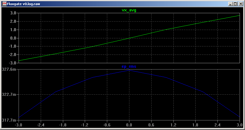
 By adding some .measure commands to the Spice file, we can plot the average (i.e. DC component) of Vx against the applied Ip. This averaging can be implemented using a simple low pass filter. We are now getting something like 1 V / A gain - excellent.
However, there's a problem: the induced voltage Ep. We see here that we will induce about 320 mV (RMS, not a sine wave!) back into the primary circuit. This is going to be a big problem if we're trying to do some measurements on a 12 V system.
 Next time we will look at a double core fluxgate to show how we can reduce Ep significantly.
Discussions
Become a Hackaday.io Member
Create an account to leave a comment. Already have an account? Log In.
i tray to make the circuit in ltspice but fail in the gain of F1, please help
Are you sure? yes | no
can you please share the files for lt spice?
thanks for you post
Are you sure? yes | no