 icstation
Step 1: Components list


1.ICStation ATMEGA2560 Mega2560 R3 Board Compatible Arduino
2.ICStation ATMEGA328 UNO V3.0 R3 Board Compatible Arduino UNO R3
3.L298N DC Motor Driver Module Robot Dual H Bridge for Arduino PIC
4.1pcs NRF24L01+2.4GHz Wireless Transceiver Module for Arduino MCU
5.KY-024 Linear Hall Magnetic Module for Arduino AVR PIC
6.For Arduino IIC/I2C/TWI 1602 Serial LCD Module Display
7.Dupont 20cm Color Cable Line 1p-1p Pin Connecto
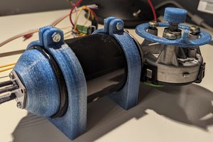
8.DC motor
Step 2: The schematic diagram of data transmission part (Connected with PC)

Step 3: The schematic diagram of the main control part( Connected with Motor)

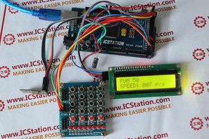
Step 4: The effect picture


Step 5: The connection of main control part

1.Connect NRF24L01 wireless transmission module to the ICStation UNO
SCK--Digital pin 13 ;MOSI-- Digital pin 11 CS——Digital pin 7;CS——Digital pin 8;MOSI-- Digital pin 12
2.Connect 1602 LCD display to the ICStation UNO
SCL—A5 ;SDA—A4
3.Connect motor drive L298N to ICStation UNO
VCC—7.2V The anode of battery GND- the cathode of battery INA—Digital pin 5; INB—Digital pin 6 OUTA-The anode of motor OUTB-the cathode of motor
4.Connect Hall Magnetic speed measurement Module to ICStation UNO
DOUT—Digital pin 3
Step 6: The connection of data acquisition transmission part

1.Connect 10uf electrolytic capacitor between ICStation Mega2560 and ground. It can reduce the shake of power supply and make the system work more stably.
2.Connect NRF24L01 wireless transmission module to the ICStation Mega 2560
SCK--Digital pin 52 ;MOSI-- Digital pin 51 MOSI--Digital pin 50;CS——Digital pin 9 CE——Digital pin 8
Step 7: Video to show the effect
http://youtu.be/0vyjQGl7LVM
 JP Gleyzes
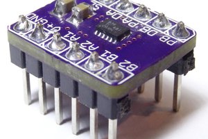
 Alex
Alex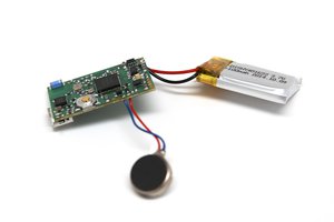
 Laura
Laura