All files posted at http://www.instructables.com/id/3D-Printed-Word-Clock/
THE LIGHT WELL
The heart of the project is the light well. It has two functions, first, create light for only the intended word (light must not bleed into adjacent words). Second, it must diffuse the light from the LEDs so that each word is evenly illuminated.
I used a two-headed 3D printer -- one print head used black ABS material to print the side walls. The second head prints a thin (0.05") layer of translucent ABS material to diffuse the light. ("Natural" ABS is milky clear. Perfect for this application.)
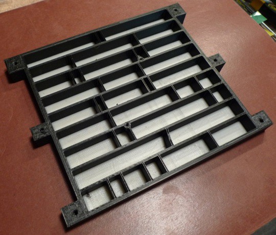
Note that the diffuse layer is not a full flat layer, which would be bad for letting light bleed across the words. Instead the diffuser portion is made up of separate rectangles for each word, positioned at the top of each light well. The divider walls extend all the way from top to bottom of the 3D printout.
Side note: If you are going to acquire a 3D printer, buy one with TWO print heads. Seriously. Two-head printers are so much more useful than one-head printers. You can use the second head to print dissolvable support material (which allows for undercuts in the models!), or to print two-color 3D models, such as this one for the clock.
THE SCHEMATICS
The next thing to do was choose the microprocessor, the clock IC, and how do you drive all of those LEDs anyway?
Microprocessor. I am very familiar Micrchip's PIC family, so I selected the PIC16F688. It costs only $1.40. Wow.
Clock IC. I wanted high accuracy, a serial interface, and battery backup. The DS3231 is perfect.
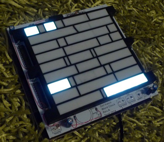
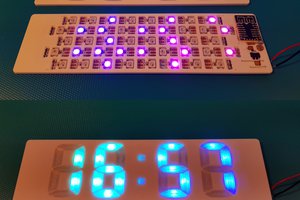
LEDs. For white light backlighting of each word, I'm using Digikey 1080-1212-1 LEDs. They are small surface-mount LEDs that can handle 30 mA of peak current. (I run them at 33% duty cycle, 30 mA which is just bright enough.) $0.14 ea, with 72 per clock.
LED Drivers. I wanted to be able to dim the LEDs when the room darkens. This makes the MAX7219 (or 7221) drivers a natural choice.
Miscellaneous. Rounding out the parts list is a small CdS photocell to detect light levels, a DIP switch for configuring clock options, push buttons to set the time, a CR2032 battery holder, and 5V regulated wall wart.
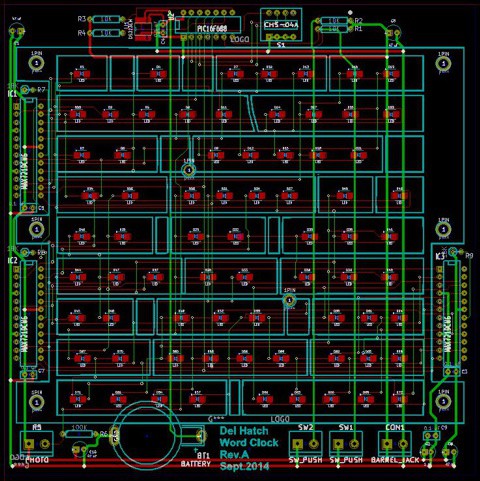
I entered the schematics using KiCAD, and then used KiCAD to layout the PC board. I can recommend KiCAD. I found that I needed to create a few schematic symbols and PC footprints, but the price is right (it is open source and free) and has a fairly good feature set. There are no board size limits, and no layer limitations. Sweet.
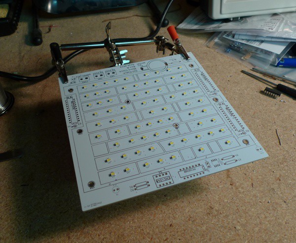
THE PC BOARD
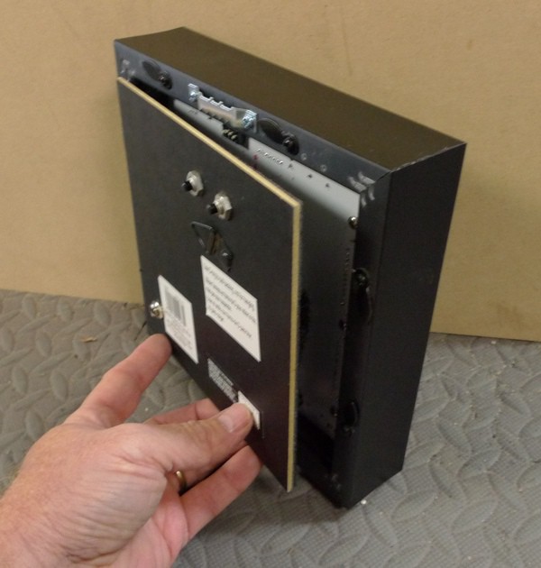
I created a PC board from the schematics. I also created a custom Christmas-themed graphic and applied it to the board as a back-layer silkscreen. This graphic is sort of a "Christmas card" when you open the back of the clock.

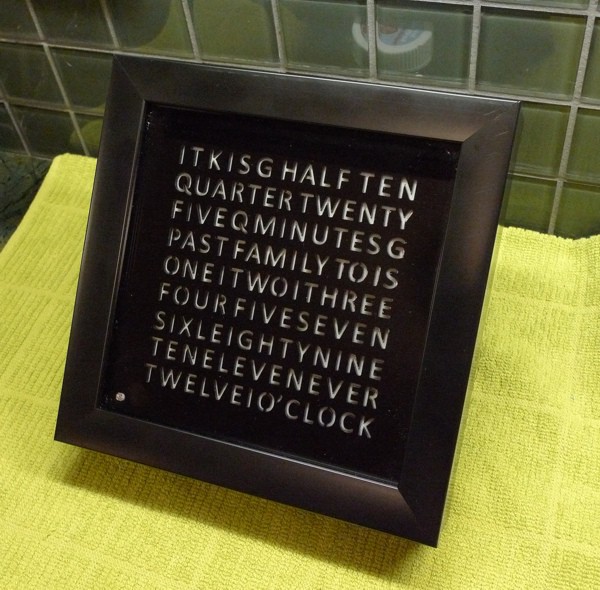
THE WORD MASK
To mask out each word, I tried a variety of materials. The winner was thin (1/16") opaque black acrylic, from Inventables.com. It cuts easily with a laser cutter, and does not bleed light.
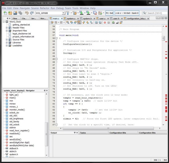
THE SOFTWARE
I used the tools provided by Microchip, which is the Eclipse-based MPLAB X Integrated Development Environment (IDE).
Microchip has a free C compiler available, the MPLAB XC compiler. It is functional and does the job, but it does not have the great C code library that the CCS compiler provides.
(Note: I like the CCS C compiler more than the MPLAB XC compiler. CCS provides so many great libraries that make configuring the microcontroller very easy, including configuring and using the ADC, the PWM module, the I/O pins, the clock configuration, etc... )
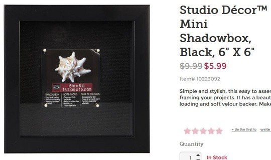
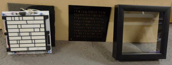
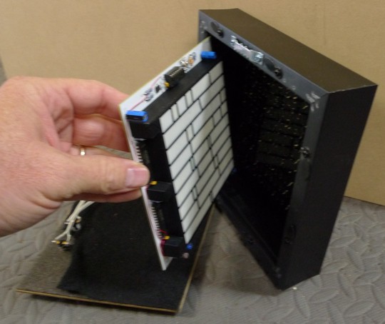
THE ENCLOSURE
I found a 6" x 6" shadow box at Michael's that looks great -- much better than I could make from scratch. And for that price?!? Perfect.
Final assembly is easy. The 3D printed light well screws to the PC board. The acrylic "word" piece fits into the shadowbox, and the PCB/light well stack slides in after that. The tight fit keeps everything aligned.
 Johan von Konow
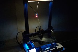
 setCREATE
 strange.rand