 icstation
Functions:
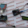
1) Uses the 4 *4 Matrix Keyboard to input the password and uses the LCD1602 to display the result. When the password is right, the LCD1602 will display "Success!". When the password is wrong, the LCD1602 will display "welcome".
2)Uses the infrared remote control to input the password and used the LCD1602 to display the result. When the password is correct, the LCD1602 will display "Success!". When the password is wrong, the LCD1602 will display "welcome".
Code for reference:
http://www.icstation.com/images/Infrared_Possword_Code.zip
Step 1: Component list:

1.1×ICStation ATMEGA2560 Mega2560 R3 Board Compatible Arduino
2.1×Bread board
3.1×10K RM103 Blue White Resistance Adjustable Resistor
4.1×1602A HD44780 Character LCD Display Module LCM Blue Backlight
6.1× Infrared Remote Control Module
7.15× Jumpers
8.15×Dupont Line
9.1×5v Power Supply
Step 2: Schematic diagram


Step 3: Connect the 5v power supply and the GND of the ICStation Mega2560 to the Bread Board.

The red line is for the power supply, the black is for the GND.
Step 4: Divide these 16 pins

Step 5: Soldering the pins to the LCD1602

Step 6: Connect the LCD1602 to the Bread Board.

Step 7: Connect the anode and cathode of the LCD1602 to the common anode and cathode

Step 8: Place the Adjustable Resistor


Pin 1-anode, Pin3-cathode, pin2-pin3(LCD1602)
Step 9: Connect the pin5 of the LCD1602 to the GND

Step 10: Connect the 1602LCD to the ICStation Mega2560.


The Pin4(1602LCD)-The Pin12(ICStation Mega2560)
The Pin6(1602LCD)-The Pin11(ICStation Mega2560)
The Pin14(LCD1602)-The Pin5(ICStation Mega2560)
The Pon13(LCD1602)-The Pin4(ICStation Mega2560)
The Pon12(LCD1602)-The Pin3(ICStation Mega2560)
The Pon11(LCD1602)-The Pin2(ICStation Mega2560)
Step 11: Connect the 4 *4 Matrix Keyboard to the ICStation Mega2560


Step 12: Connect the Infrared remote control module to the pin7of the ICStation Mega2560, the GND and the anode

Step 13: Video to show effect.


 Marcin Saj
 Justin Scott
 dkrum
dkrum