-
1Step 1
![]()
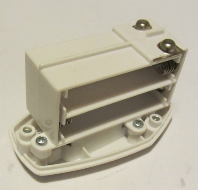
Unscrew the three screws holding the battery compartment in place. Remove battery compartment. Remove batteries,
-
2Step 2
![]()
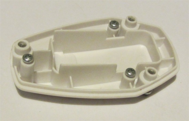
Unscrew the three screws holding the battery box in place. Separate the battery box from the backplate. You won't be needing this unless you ever want to undo the battery mod. Screw the screws into the backplate so you don't lose them.
-
3Step 3
![]()
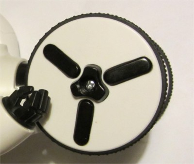
Dismantle MIP, starting by removing the wheels. To do this, you need to pry the plastic hub cap from each wheel. This is a one way trip. They're not going back on, but consider it a badge of honour for your MIP. A scalpel does the job nicely. Removing the plastic hub cap exposes a screw that fastens the wheel to the motor shaft. Unscrew that screw to remove the wheel. Remove both wheels., then unscrew the 6 screws on the back of the MIP. At this point you can prise apart the two halve's of MIP's body.
-
4Step 4
![]()
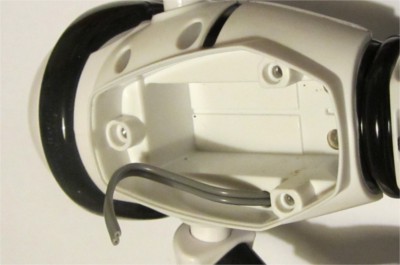
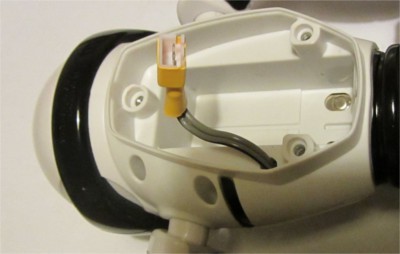
Have a good look around inside MIP. Look for a place to drill a hole to poke through a battery lead from the battery compartment, through to the inside of MIP. You can see where I drilled mine in the picture above. A 4mm hole did the job. Tie a knot in the cable and feed it through the hole, from the inside of the MIP. The knot provides a bit of strain relief.
-
5Step 5
![]()
Terminate the end of the cable in the battery compartment with the three pin male connector. You need to terminate the 2 end pins (leave the middle pin disconnected). To get the polarity right, plug the female connector into the male connector so you can see which pins are connected to the yellow wire (ground) and red (7.4V). the black wire (middle pin) is only used during charging, so isn't connected to MIP.
Before you start soldering, think about heatshrink. You want to insulate both connections, and it doesn't hurt to heatshrink the whole back of the male connector, as shown in the picture.
-
6Step 6
![]()
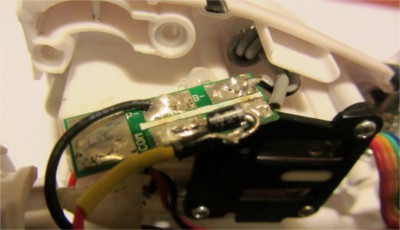
Time to install the LiPo protection module. I put this in MIP because it's pretty small and makes the battery packs smaller and cheaper. There's a nice nook to fit this into. Solder the new battery lead to the terminals marked B+/B-. Make sure you get the wires around the right way. While you're at it, solder short lengths of wire to the P+/P- pads on the protection PCB. older one or two 1N4004 diodes in series in the positive lead to drop the voltage. I'm currently using two diodes which drops the voltage to MIP to about 6.2V. Use some heatsgrink around the diode.
Without the diode(s), you'll end up with a MIP that's pretty twitchy on a freshly charged battery pack, with a tendency to over compensate when bumping into obstacles. I toyed with putting in a small RC 6V BEC, but then it needs to be powered off. In the end the easiest thing was to put a 1N4004 diode between the P+ pad on the protection PCB and the red lead. 1 diode drop results in a snappy MIP. 2 diodes in series brings MIP's behaviour in line with what I get when running on AAA batteries.
-
7Step 7
![]()
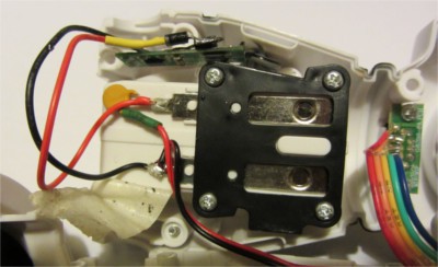
You'll see a bit of masking tape above the battery compartment. Peel it back and you'll see two solder joints. You need to solder the other ends of the wires you just soldered to the P+/P- pads in the previous step. Use the picture to work out which terminal is which. The red wire is positive.
-
8Step 8
![]()
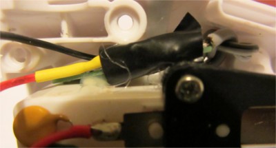
The final thing to do is to secure the LiPo protection module with a couple of dabs of hot glue. Note that I've stuck a bit of electrical tape to make sure the diode legs don't touch MIP's PCB.
-
9Step 9
![]()
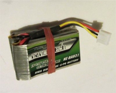
Screw everything back together, and you've finished the MIP mods. Next, we make the battery packs. Pull out your LiPos. and cut the connectors off.. Careful not to short the leads. Connect the batteries in series, slide heatshrink on and then solder on the flying leads of the JST-XH connector. Yellow is ground, black is the series connection (3.7V) and red is +V (7.4V). I held the two LiPos together with an elastic band. After everything is soldered, shrink down the heatshrink.
-
10Step 10
Sanity check time. Don't connect the battery to MIP just yet. The original connections in the battery compartment are still in place, so check that the +ve connection (look at the AAA holder that you pulled out) is connected to the +ve lead of your battery wire. Do the same for -ve. Double check that you've wired the male connector correctly by looking at the wire colours on the battery pack. Measure the voltage of the battery pack. Check that everything correlates, and them power MIP up.
Discussions
Become a Hackaday.io Member
Create an account to leave a comment. Already have an account? Log In.