 Mike Szczys
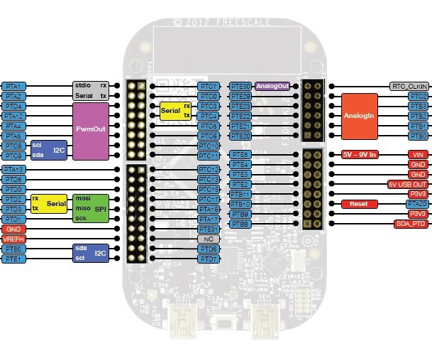
Both of the robot bodies we will provide for the Roboto workshop use servo motors. That means the first task you have in front of you is to set up the PWM with the proper timing for driving servo motors.
My advice is to first use PWM to dim an LED on the board you have chosen. This gives immediate feedback that you have things working.
From there you must implement the following timing:
- Period of exactly 20ms
- Pulse Widths (the time the pin is high):
- 1ms moves the servo to its limit in one direction
- 2ms moves the servo to its limit in the other direction
- 1.5ms centers the servo motor
In the case of the wheeled robs the 1 and 2 ms widths will move the motors forward or back while the 1.5ms timing will stop the movement.
In the case of the MeARM the settings between 1 and 2ms will position the arm. I suggest writing a function wrapper that can divide up the with into increments of 180 (for positioning in degrees). Moving 1 degree every 15ms results in fairly reliably motion for me.


 deʃhipu
 Jarich
 biemster
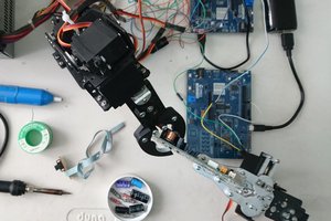
 Guillermo Perez Guillen
Not sure if you are planning on using AVRs, but if you are, feel free to steal / modify / abuse my PWM code. You can drive as many waveforms as you have available pins, with the only limitation being that you must run all pins at the same period (20ms for servos). It is very efficient (I can generate a clean signal on 21 pins using a 12MHz clock wile still doing all sorts of stuff in the main control loop).
See http://git.digitalcave.ca/gitweb/?p=projects.git;a=tree;f=lib/avr/pwm;hb=HEAD for the code, and the Stubby project for a sample implementation using it.
Cheers