 Mike Szczys
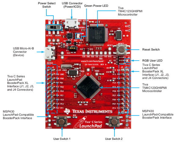
Use the TivaWare peripheral library to get PWM working on the Tiva C launchpad: http://www.ti.com/tool/sw-tm4c
I made an example of dimming LEDs that can be complied with GCC: https://github.com/szczys/tiva-c-launchpad-hardware-pwm/blob/master/main.c
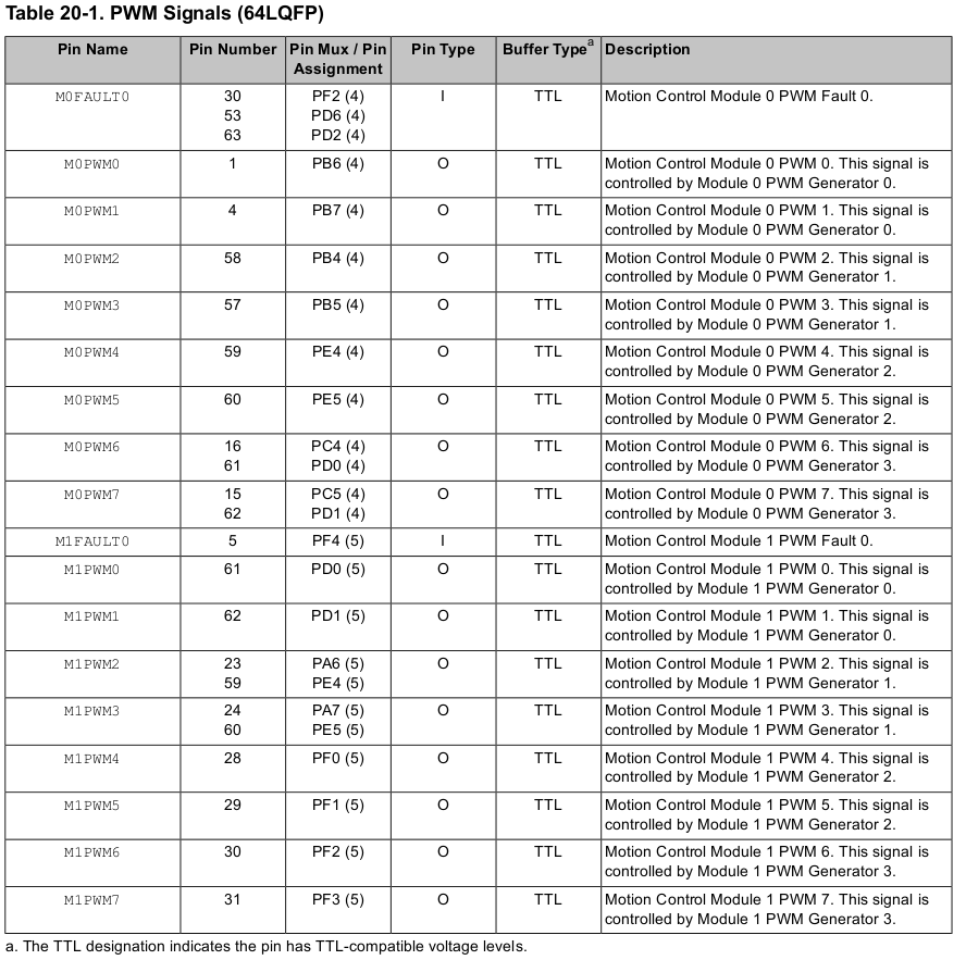
Specific code for servo timing is found below. The datasheet for the TM4C123GH6PM includes this table which can be used to find out the PWM module, generator, pin, and other values:
/*################################################
# Hardware PWM proof of concept using
# the Tiva C Launchpad
#
# Started with example code by
# lawrence_jeff found here:
# http://forum.stellarisiti.com/topic/707-using-hardware-pwm-on-tiva-launchpad/
#
# Altered to use code found on section
# 22.3 of the TivaWare Peripheral Driver
# Library User's Guide found here:
# http://www.ti.com/lit/ug/spmu298a/spmu298a.pdf
#
#
# This example drives servo motors on PF1, PF2, and PF3
#
#################################################*/


#include "driverlib/pin_map.h"
#include <stdint.h>
#include <stdbool.h>
#include "inc/hw_gpio.h"
#include "inc/hw_types.h"
#include "inc/hw_memmap.h"
#include "driverlib/sysctl.h"
#include "driverlib/pin_map.h"
#include "driverlib/gpio.h"
#include "driverlib/pwm.h"

void delayMS(int ms) {
    SysCtlDelay( (SysCtlClockGet()/(3*1000))*ms ) ;
}

int
main(void)
{
    uint32_t period = 5000; //20ms (16Mhz / 64pwm_divider / 50)
    uint32_t duty = 250;    //1.5ms pulse width

    //Set the clock
   SysCtlClockSet(SYSCTL_SYSDIV_1 | SYSCTL_USE_OSC |   SYSCTL_OSC_MAIN | SYSCTL_XTAL_16MHZ);

   //Configure PWM Clock divide system clock by 64
   SysCtlPWMClockSet(SYSCTL_PWMDIV_64);

   // Enable the peripherals used by this program.
    SysCtlPeripheralEnable(SYSCTL_PERIPH_GPIOF);
    SysCtlPeripheralEnable(SYSCTL_PERIPH_PWM1);  //The Tiva Launchpad has two modules (0 and 1). Module 1 covers the LED pins

    //Configure PF1,PF2,PF3 Pins as PWM
    GPIOPinConfigure(GPIO_PF1_M1PWM5);
    GPIOPinConfigure(GPIO_PF2_M1PWM6);
    GPIOPinConfigure(GPIO_PF3_M1PWM7);
    GPIOPinTypePWM(GPIO_PORTF_BASE, GPIO_PIN_1 | GPIO_PIN_2 | GPIO_PIN_3);

    //Configure PWM Options
    //PWM_GEN_2 Covers M1PWM4 and M1PWM5
    //PWM_GEN_3 Covers M1PWM6 and M1PWM7
    PWMGenConfigure(PWM1_BASE, PWM_GEN_2, PWM_GEN_MODE_DOWN | PWM_GEN_MODE_NO_SYNC);
    PWMGenConfigure(PWM1_BASE, PWM_GEN_3, PWM_GEN_MODE_DOWN | PWM_GEN_MODE_NO_SYNC);

    //Set the Period (expressed in clock ticks)
    PWMGenPeriodSet(PWM1_BASE, PWM_GEN_2, period);
    PWMGenPeriodSet(PWM1_BASE, PWM_GEN_3, period);

    //Set PWM duty
    PWMPulseWidthSet(PWM1_BASE, PWM_OUT_5,duty);
    PWMPulseWidthSet(PWM1_BASE, PWM_OUT_6,duty);
    PWMPulseWidthSet(PWM1_BASE, PWM_OUT_7,duty);

    // Enable the PWM generator
    PWMGenEnable(PWM1_BASE, PWM_GEN_2);
    PWMGenEnable(PWM1_BASE, PWM_GEN_3);

    // Turn on the Output pins
    PWMOutputState(PWM1_BASE, PWM_OUT_5_BIT | PWM_OUT_6_BIT | PWM_OUT_7_BIT, true);

    while(1)
    {
        delayMS(2000);

        //Drive servo to 135 degrees
        PWMPulseWidthSet(PWM1_BASE, PWM_OUT_5,duty+(duty/2));
        PWMPulseWidthSet(PWM1_BASE, PWM_OUT_6,duty+(duty/2));
        PWMPulseWidthSet(PWM1_BASE, PWM_OUT_7,duty+(duty/2));

        delayMS(2000);

        //Drive servo to 90 degrees
        PWMPulseWidthSet(PWM1_BASE, PWM_OUT_5,duty);
        PWMPulseWidthSet(PWM1_BASE, PWM_OUT_6,duty);
        PWMPulseWidthSet(PWM1_BASE, PWM_OUT_7,duty);

    }

}
Discussions
Become a Hackaday.io Member
Create an account to leave a comment. Already have an account? Log In.
how did you calculate period and duty cycle..........what is the system clock frequency that you set???
Are you sure? yes | no