 zakqwy
Thanks for checking out NeuroBytes!
This Project Details section is current as of 10/29/2018. To see the previous edition, follow this link.
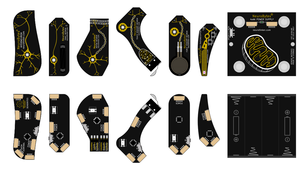
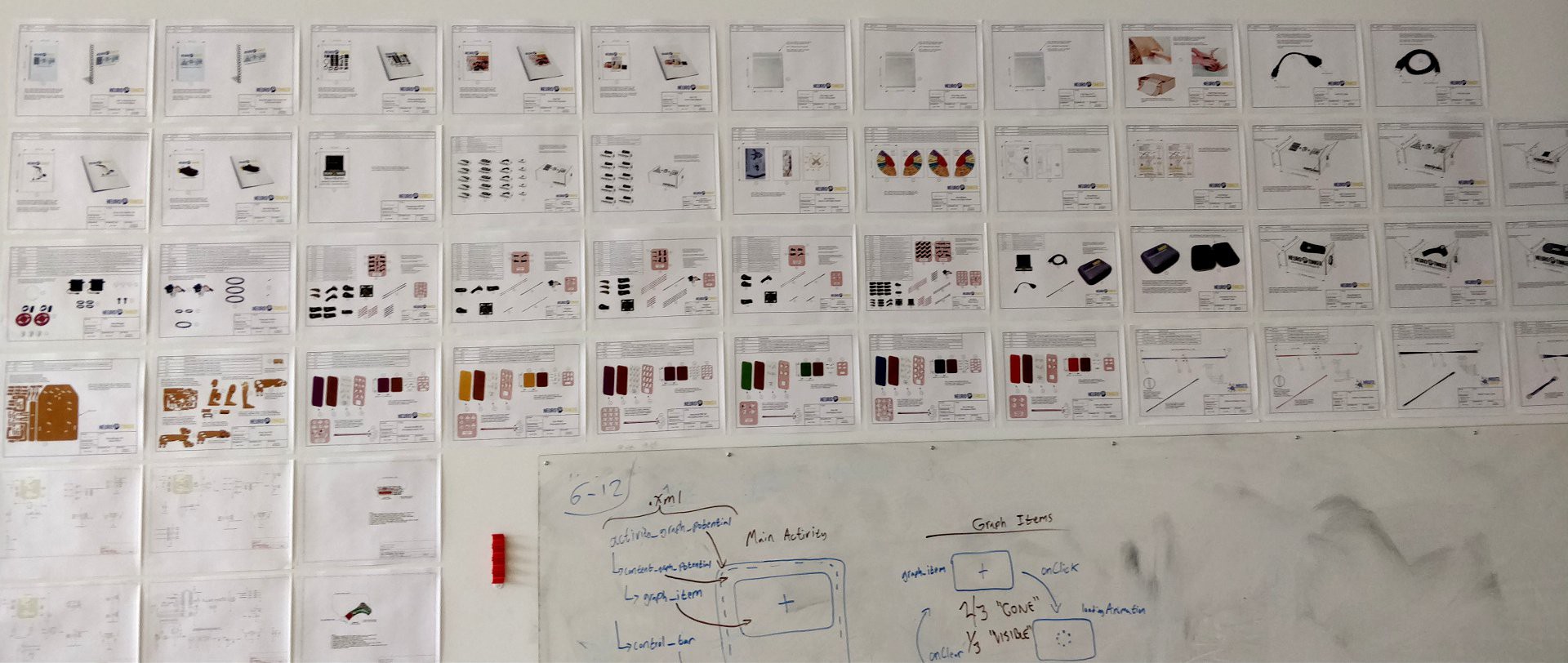
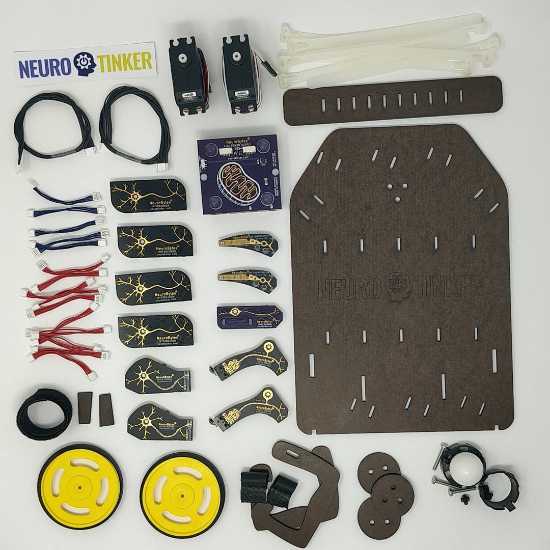
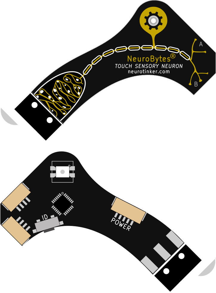
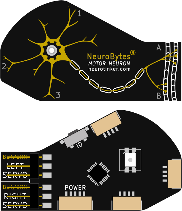
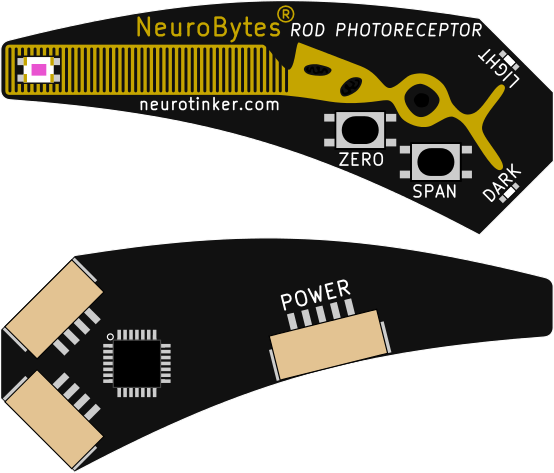
[Above: 3+ years of NeuroBytes evolution. The new boards have different connectors, different microcontrollers, different graphics, different LEDs, different communication protocols, and ... well, different just-about-everthing. Below: the current NeuroBytes ecosystem as rendered from the original PCB designs, all of which are in production. Left to Right: Interneuron, Tonic Neuron, Motor Neuron, Touch Sensory Neuron, Pressure Sensory Neuron, Rod Photoreceptor, Battery Pack. Accessories and other prototypes not shown...]
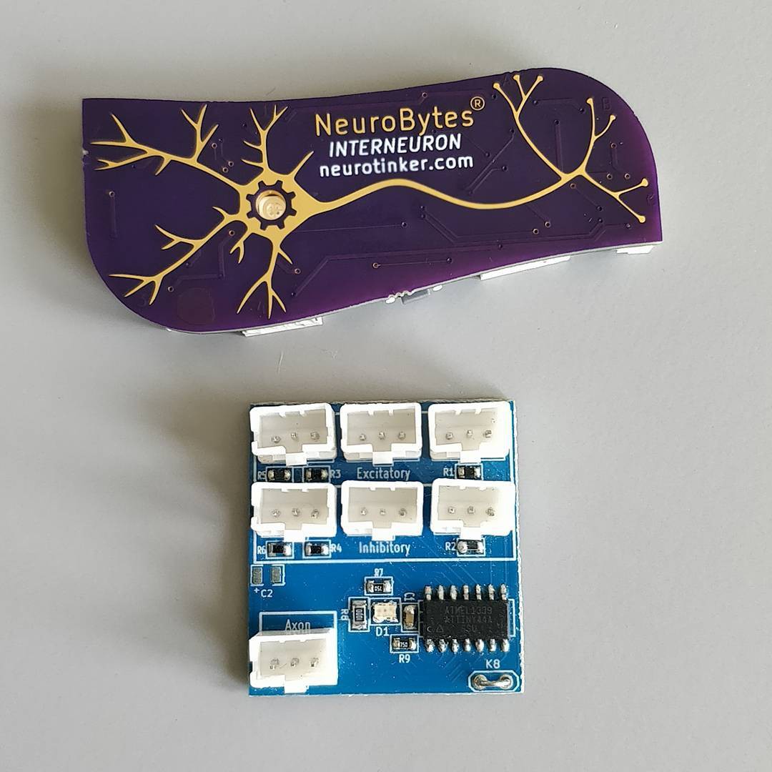
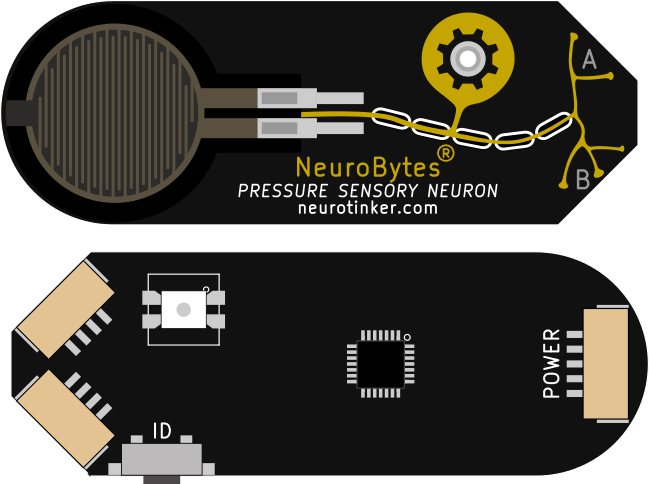
 NeuroBytes® are open-source electronic neuron simulators designed to help students understand basic neuroscience. Each module can be freely connected with others to form complex and biologically representative neural networks. On-board reverse-mounted RGB LEDs indicate current state: excited, inhibited, firing, learning, etc. The boards are based on the STM32L0 ARM Cortex M0+ microcontroller and the libopencm3 hardware library, and communicate via a novel board-to-board networking protocol that allows central data collection and global message broadcasting.
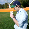
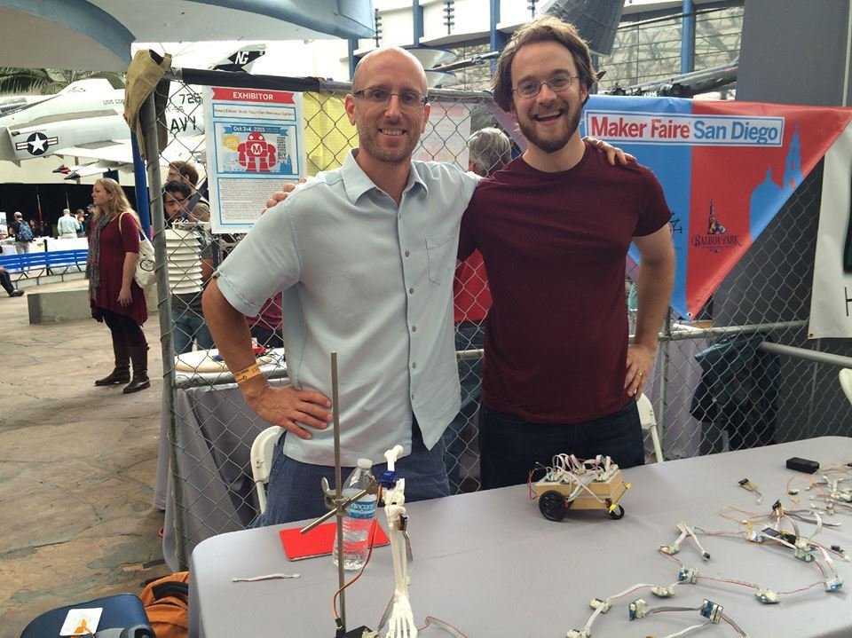 [img: NeuroTinker co-founders Joe (left) and Zach (right) at San Diego Maker Faire 2015]
Since its inception in mid-2012 and hardware development starting in February of 2014, this project has gone through many iterations and spawned the formation of NeuroTinker, LLC, a for-profit company primarily funded via Phase I and Phase II SBIR grants from the National Science Foundation. Our six NeuroBytes kits -- the Skin Kit, the Eye Kit, the Knee Jerk Reflex Kit, the NeuroBuggy Kit, the Advanced NID Kit, and the Standalone NID KIt -- are currently in production and are scheduled to ship to our Kickstarter backers and other early adopters fall 2018.
Open Source Hardware
NeuroBytes is Open Source Hardware, as defined by OSHWA and standardized under their Certification Program (US000024 for the ATtiny88-based v0.91 boards, US0108 through US0115 for the current STM32L0 devices). Our design files (C code for firmware and KiCAD files for hardware) are released under the terms of CC-BY-SA 4.0 as detailed in our license file.
Resources
NeuroTinker GitHub Repositories. The firmware and hardware files for this project are released under CC-BY-SA 4.0 and the latest version will always live in the linked GitHub organization. Individual boards and support items are listed under individual repos (Interneuron, Motor Neuron, etc).
NeuroTinker company site. This is where we share additional information related to the NeuroBytes product line, such as operating instructions, kit purchase links, and social media account info. We have a public forum on the site that sees occasional use, and a spot to sign up for infrequent email newsletters that make every effort to consolidate important info into one location.
This project page. Yes, the project page you are currently reading. New project logs will appear somewhat frequently and tend to provide a good up-to-the-minute record of technical challenges and developments; conversely, if you want an exhaustive history of NeuroBytes you can start at the beginning. We've had a few great conversations in the log page comment sections (along with the main comment section), so don't hesitate to provide your input.
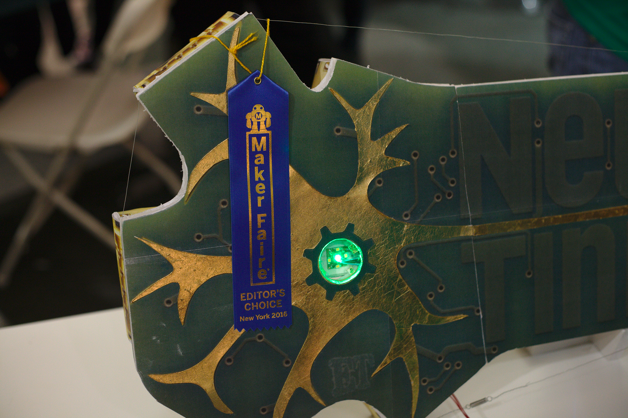 [img: jumbo-sized and functional NeuroBytes v0.91 board built for World Maker Faire 2016.]


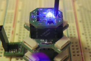
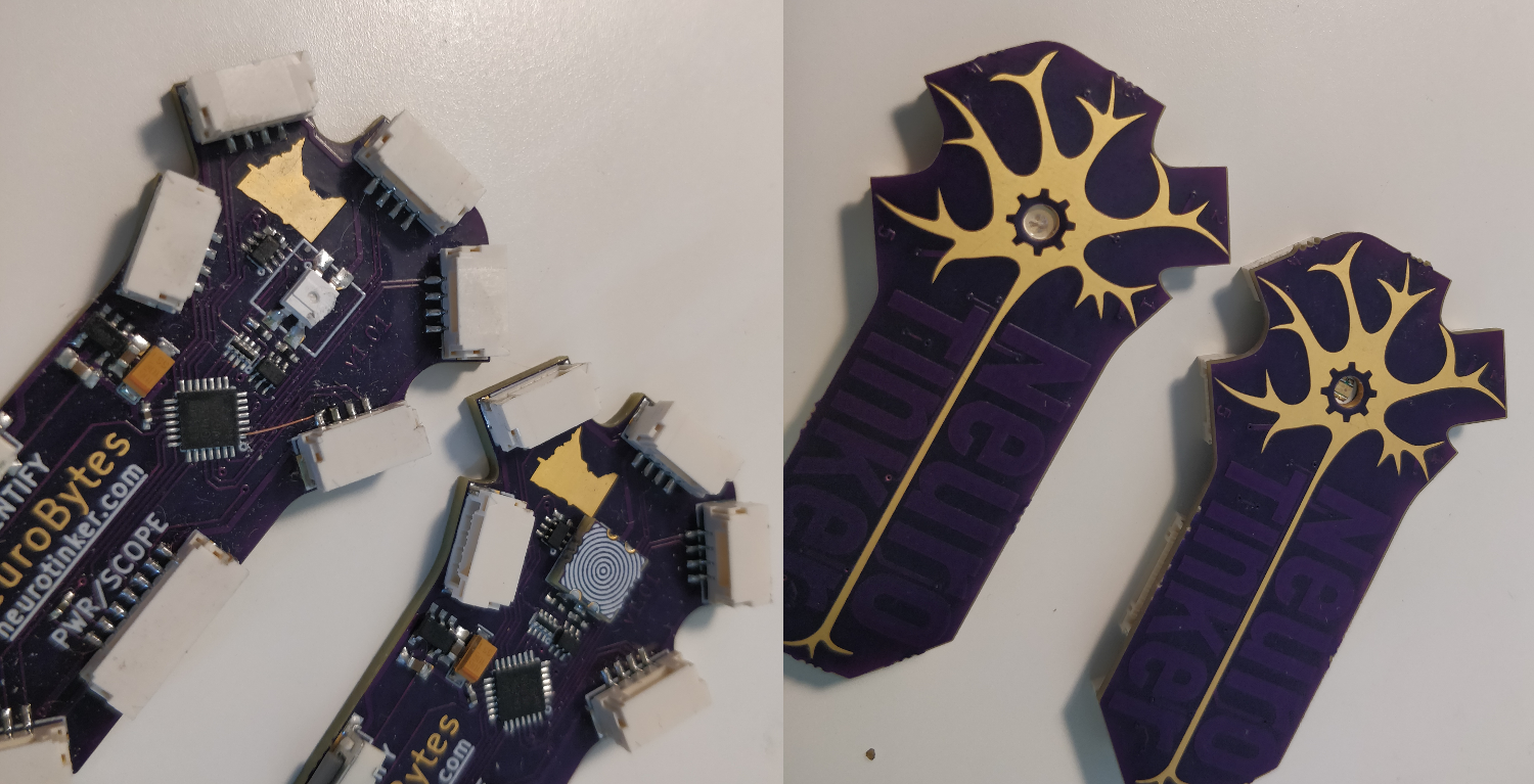 The boards look a bit different but the LED effect is the same. And I included a sweet concentric circle silkscreen pattern on the back for good measure. I think I did forget a polarity alignment mark though.
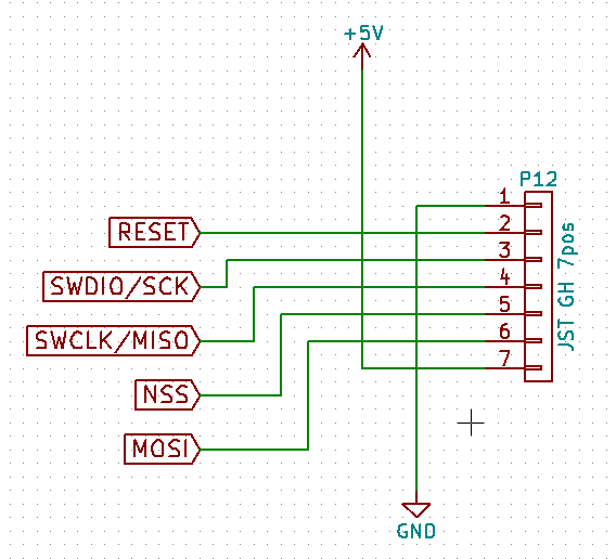 We eventually ran into issues with the 7-pin JST GH connector; the plastic webbing on the top of the connector spanned far enough that it was easy to damage. The clear answer was to ditch the SPI NSS and MOSI lines and move to a 5-pin connector.
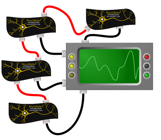 Black wires are 'scope data, red cables are NeuroBytes impulses. Problem: cables are expensive and tend to get out of control when you have a lot of them in a small space. Jarod thought we could do it like this:
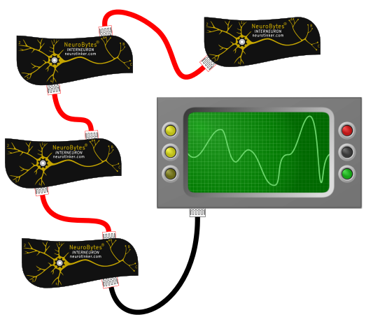 The NeuroBytes would send data along the same cables as they originally sent simple pulses...
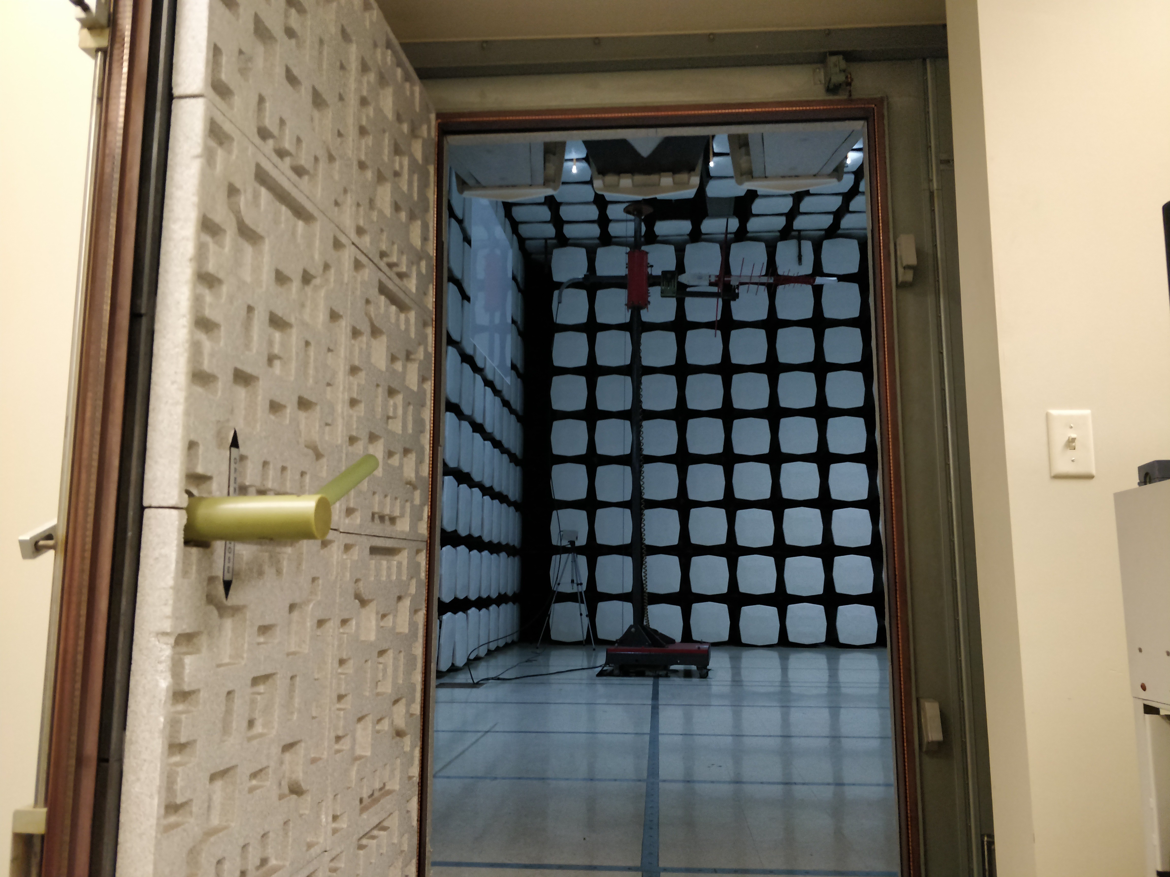
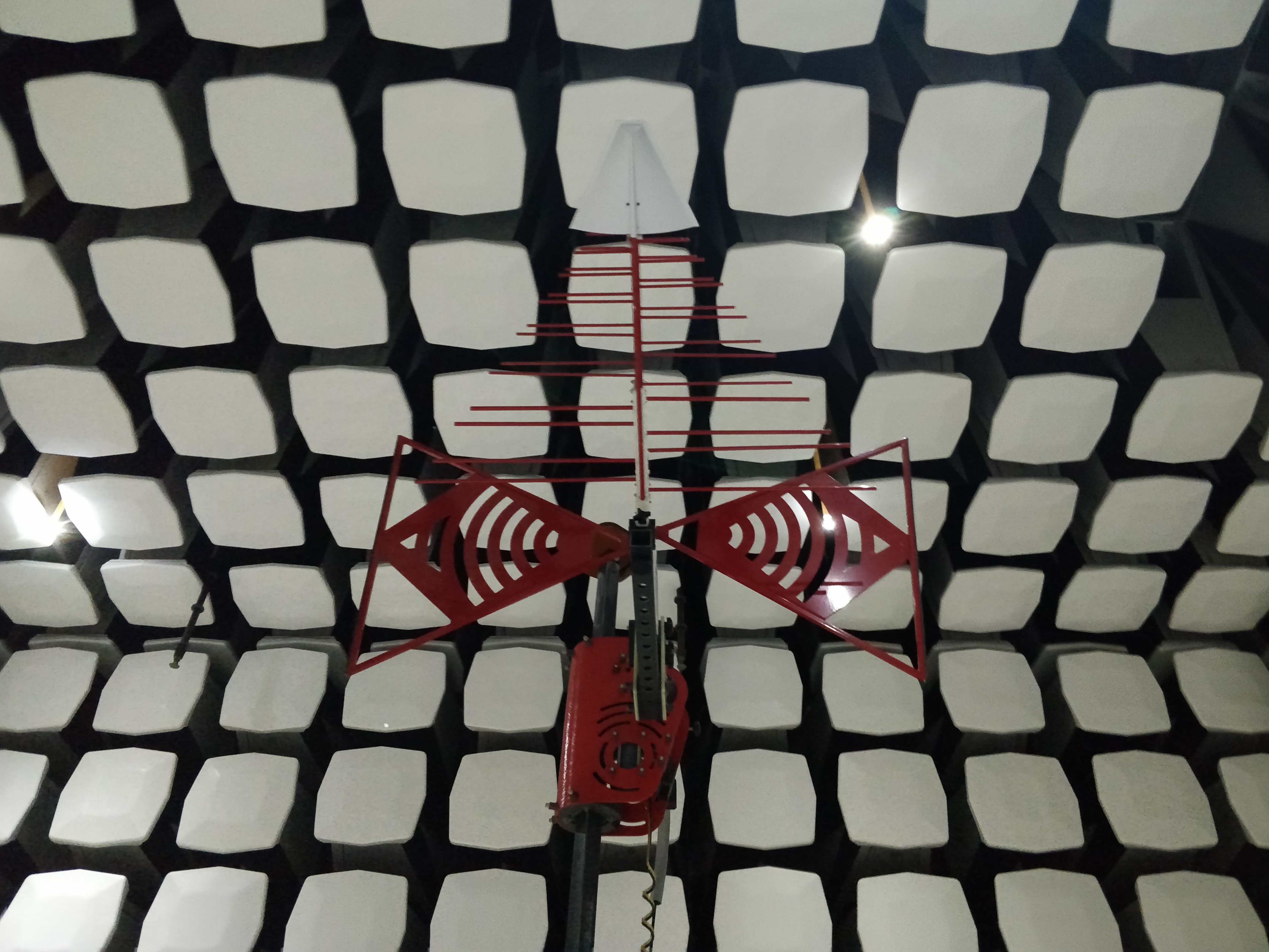
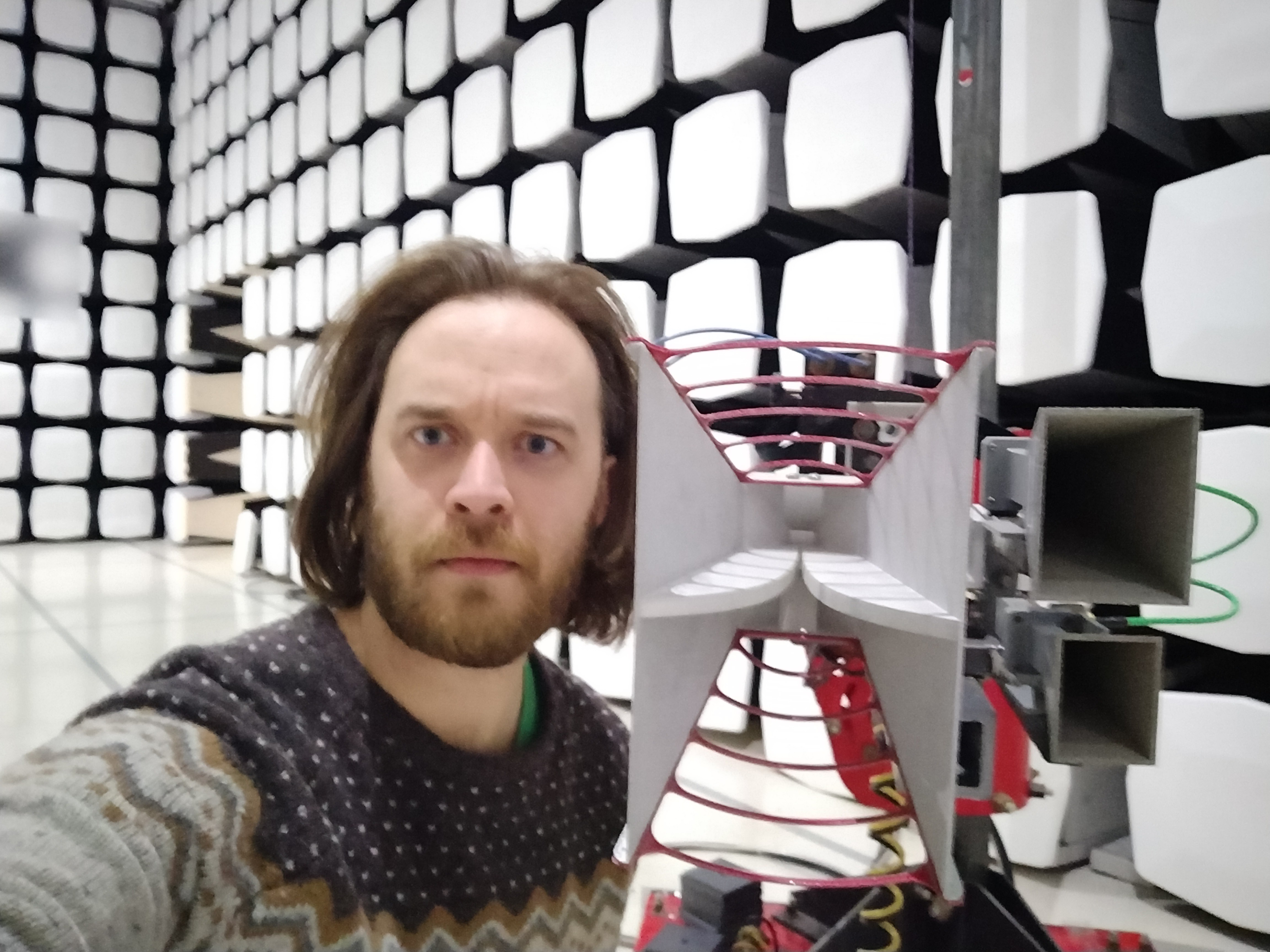
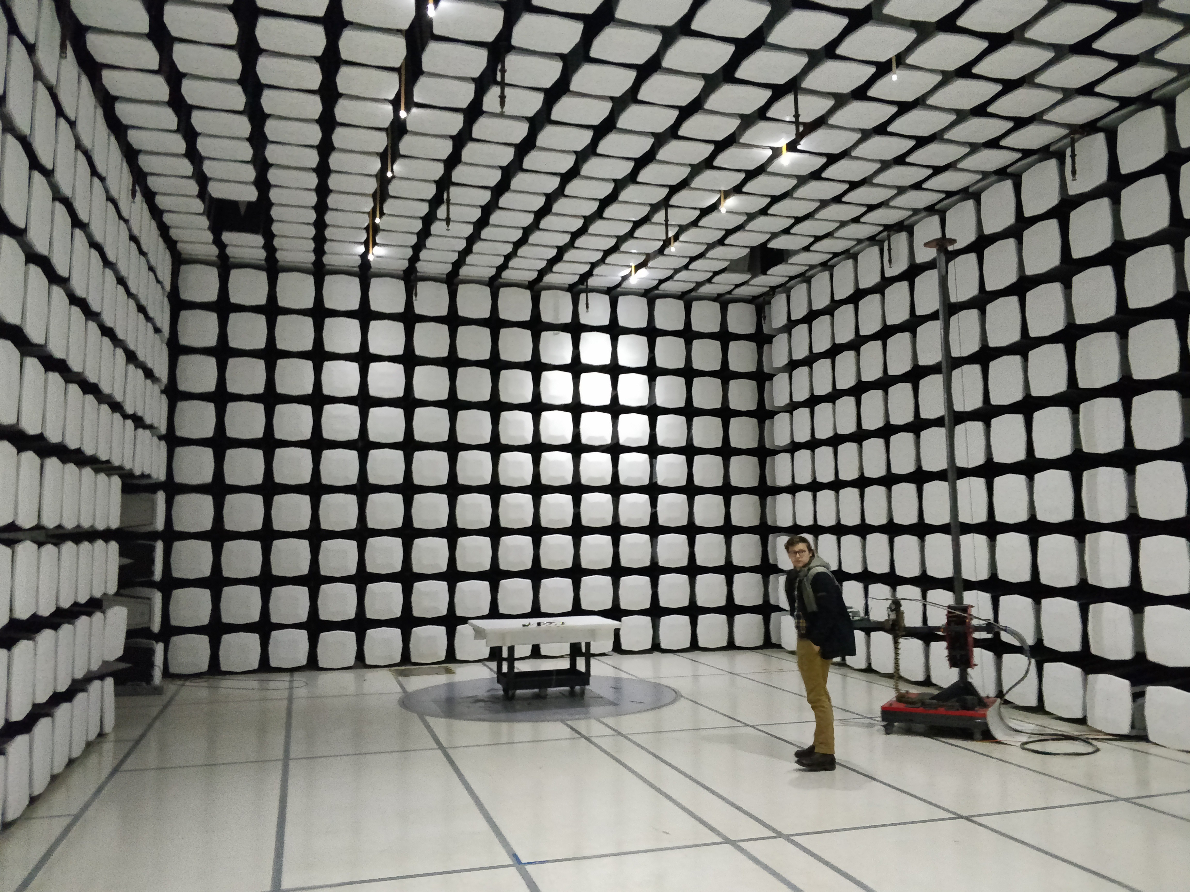
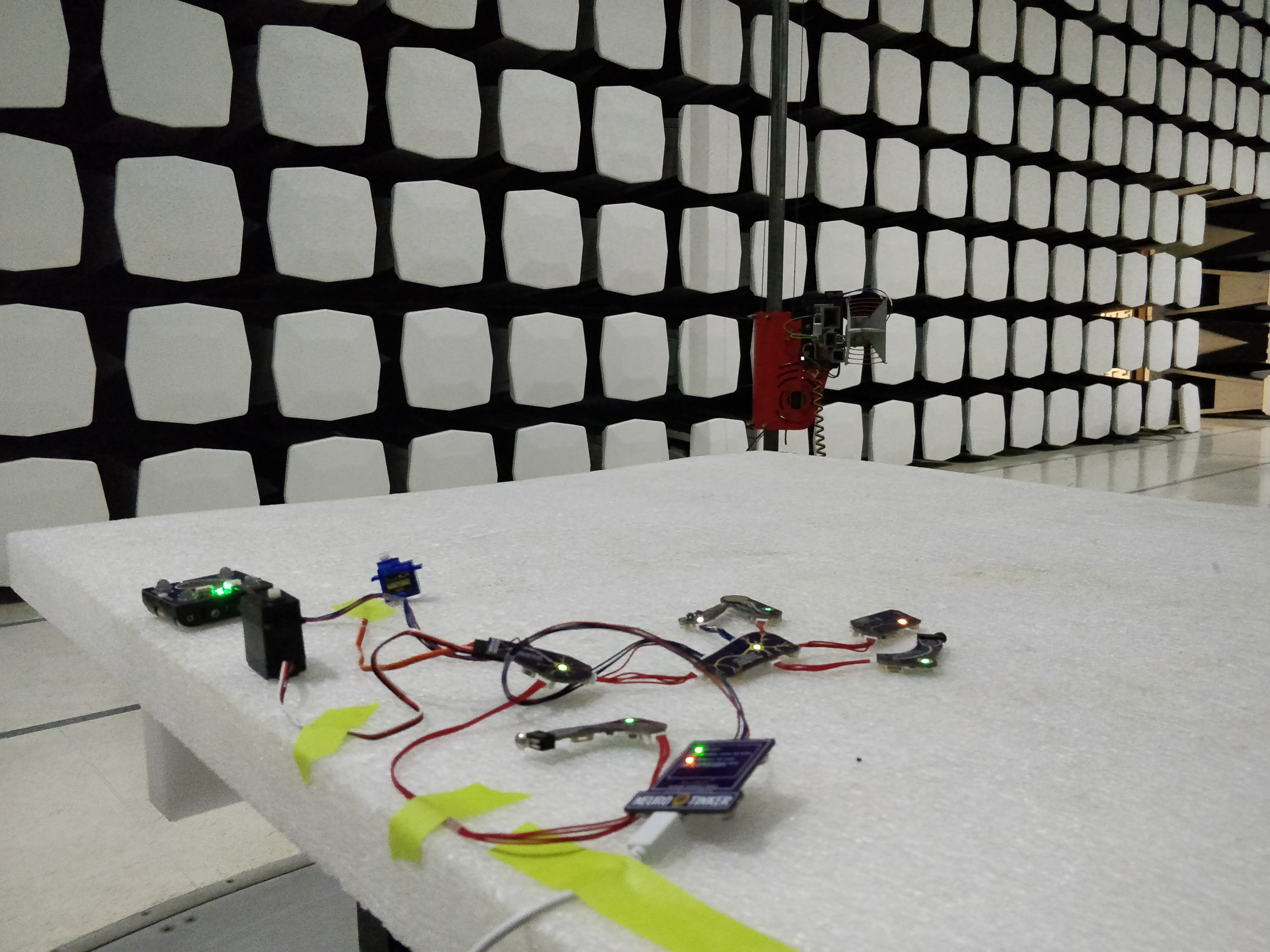
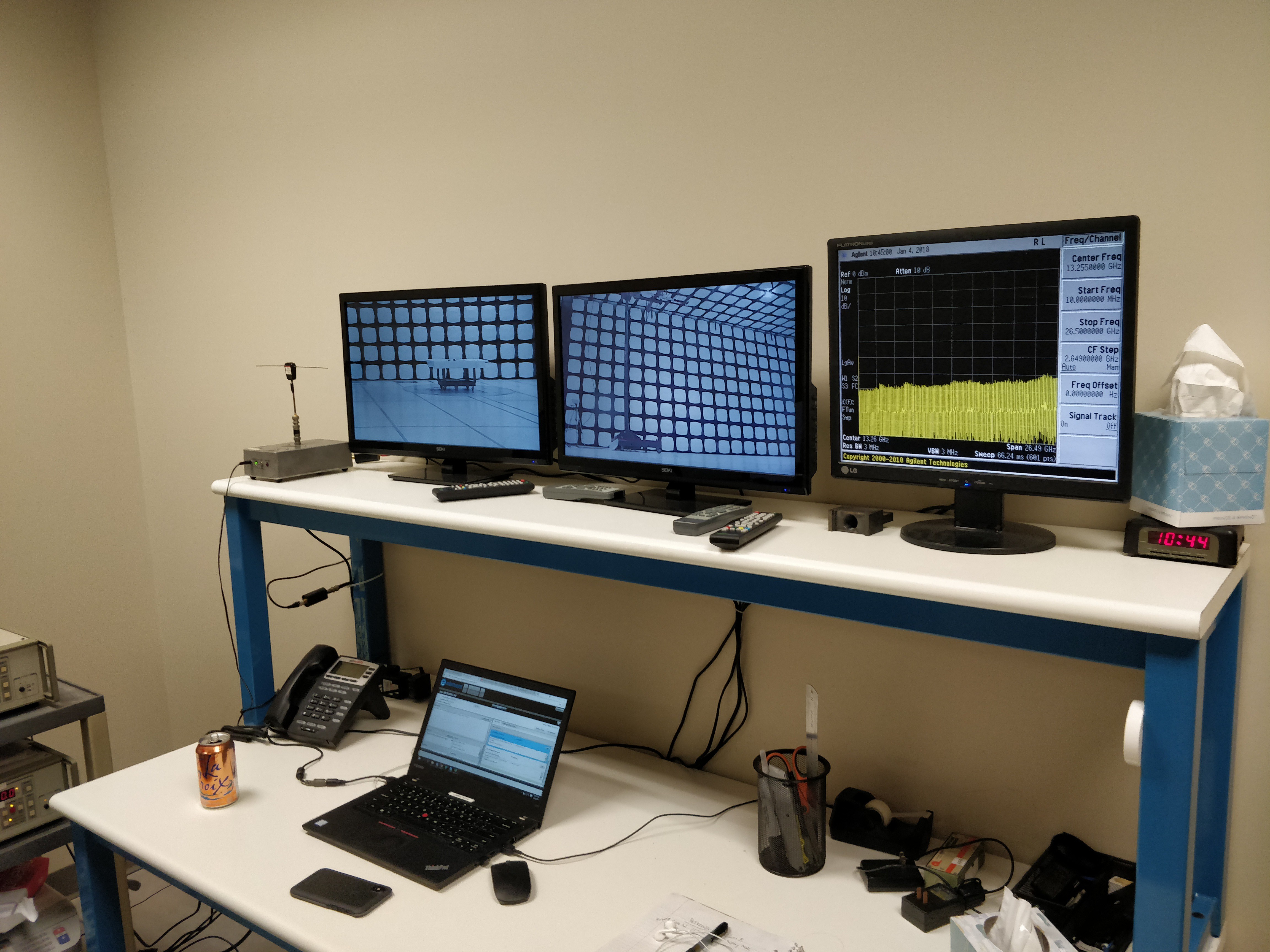
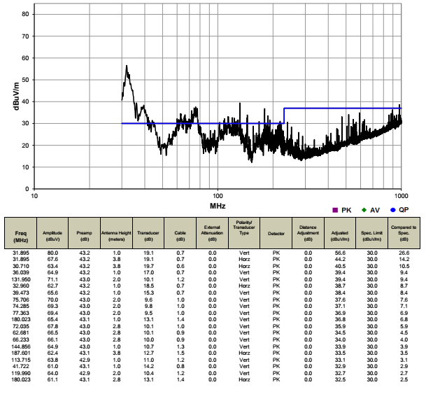 Above, a full NeuroBytes network test with the NID attached and the tablet graphing real-time data. This graph shows raw cumulative test data and we didn't actually fail in all the spots shown; after running through the quasi-peak detector we found that the first big hump (~30 MHz - 40 MHz) is the one we need to worry about.
 Above, maybe we're on the right track going after the USB cable? The 32 MHz peak is down quite a bit, but the 39 MHz peak jumped a few dBuV/m...

 [above, our NeuroBuggy Kit. Designed for building Braitenberg Vehicles and playing around with simple neural network-controlled robotics.]
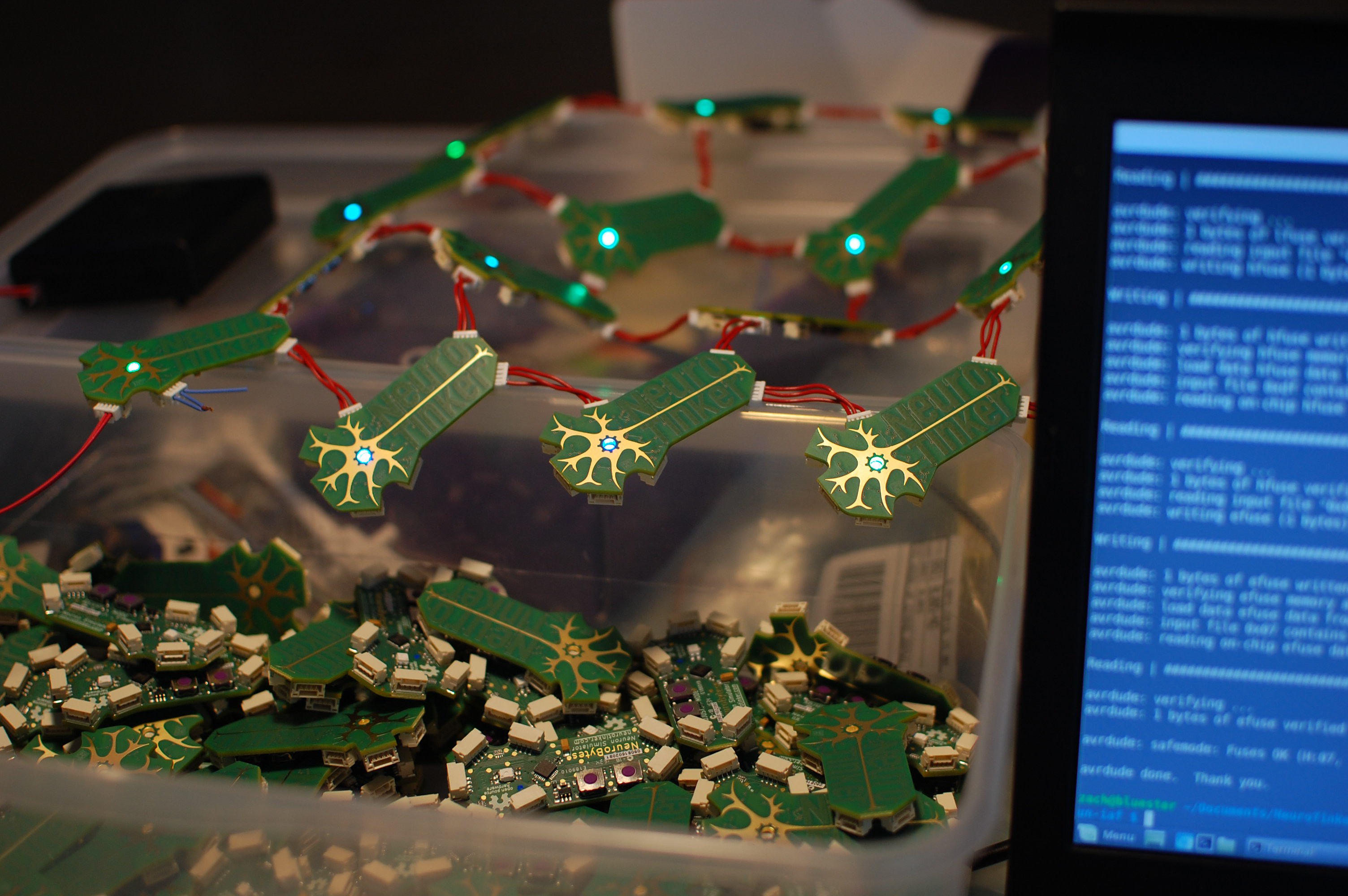
 [img: jumbo-sized and functional NeuroBytes board built for World Maker Faire 2016.]
 In two(ish) months we are launching a crowdfunding campaign (I know... 'ugh'. Agreed. I promise to keep my project log spam to a minimum) with the following nearly finalized boards:
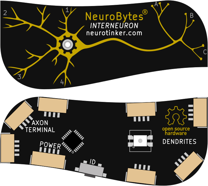


 wolfgangouille
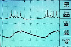
 Bruce Land
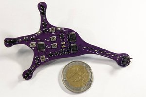
 Rollyn01
That's amazing. We met some time ago on youtube, didn't have time to pursue this project much but I added it on hackaday.io too. Code name Neurino. I am really surprised by how much the two projects converged. Well done.