 zakqwy
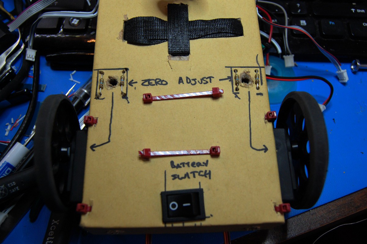
I'm not sure if this is the right way to do notation--open (always) to suggestions. In any case, this is how NeuroBuggy's brain was wired up for yesterday's video:
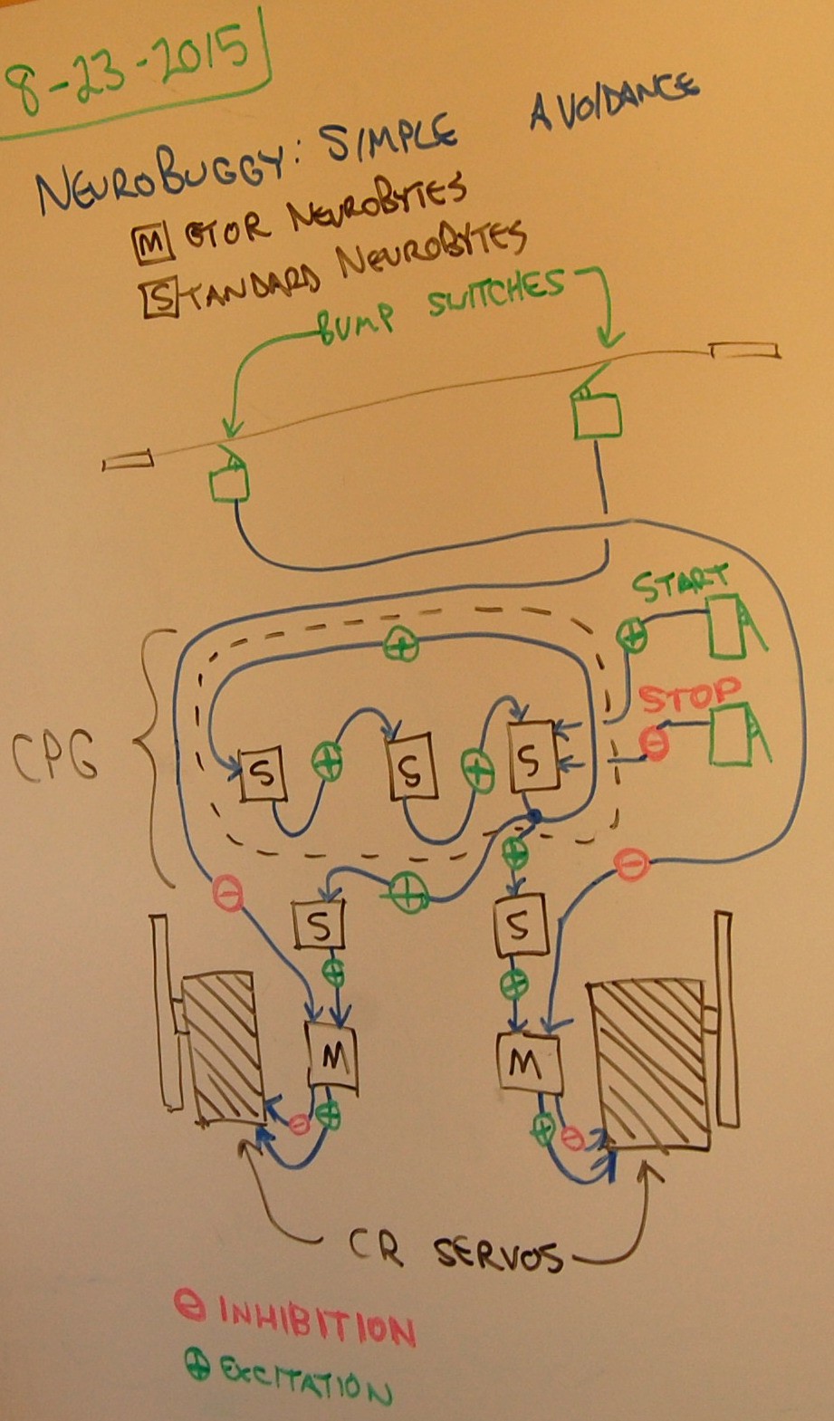
Hitting the START button kicks off the Central Pattern Generator (CPG), which runs continuously as a 3-NeuroBytes loop. The STOP button inhibits one of the members of that loop, causing the pulse to die after a second. Note that both of these switches are combined into a single double switch unit.
Once the CPG is running, an Axon Terminal (the blue ball at the lower right of the CPG) starts dumping pulses into another pair of NeuroBytes, which then feed into the two Motor NeuroBytes. The pulse generator operates quickly enough that the next pulse comes along before each Motor NeuroBytes board stops spinning its servo; thus, this circuit produces continuous rotation. The Motor NeuroBytes boards are actually mirror images of each other in firmware terms, so sending excitatory pulses to each one spins their respective servos in opposite directions (which ends up being 'forward', since they're mounted 180 degrees apart).
When one of the bump switches contacts an object in my living room, it immediately hits the inhibitory input of the opposite Motor NeuroBytes board. This overrides the last pulse seen by that board and causes it to spin in reverse for a short time, causing NeuroBuggy to rotate away from the object. Both servos start spinning in one direction once the next CPG pulse comes around.
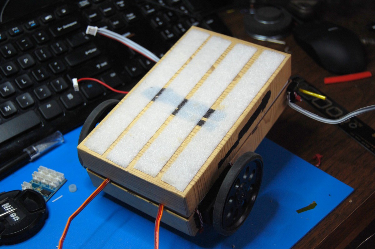
To put this circuit into action, we start with a blank NeuroBuggy:
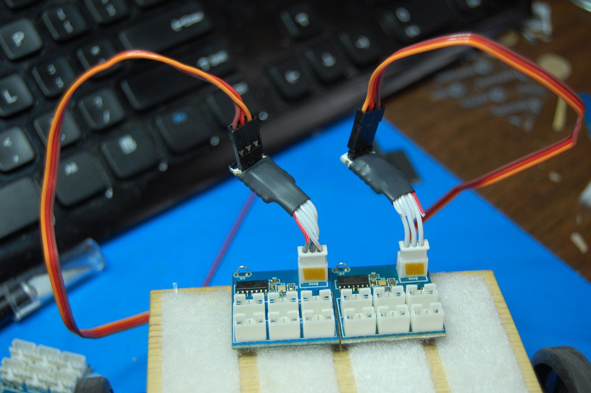
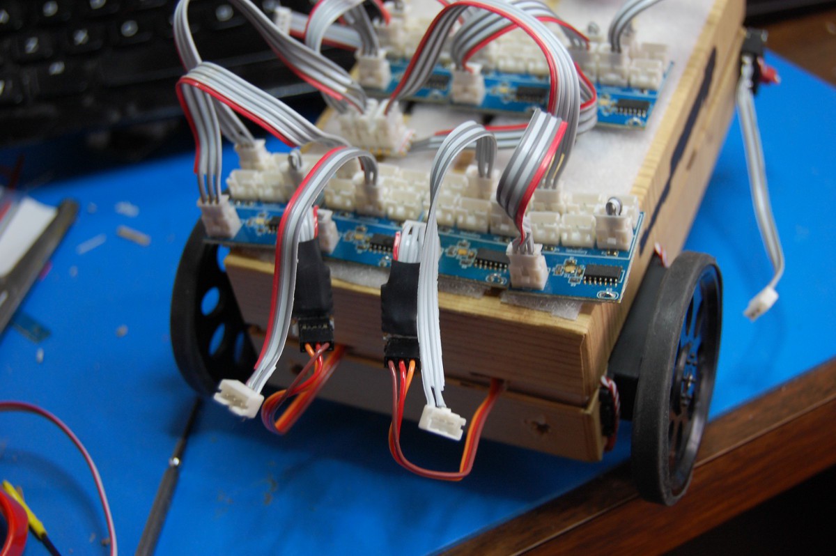
Starting from the drive end, we add the two Motor NeuroBytes:
... plug them into the servos:
... and tuck the excess wire back into the chassis:
A quick test with an extra switch shows the Motor NeuroBytes are properly programmed (cyan = CR servo version) and working as intended:
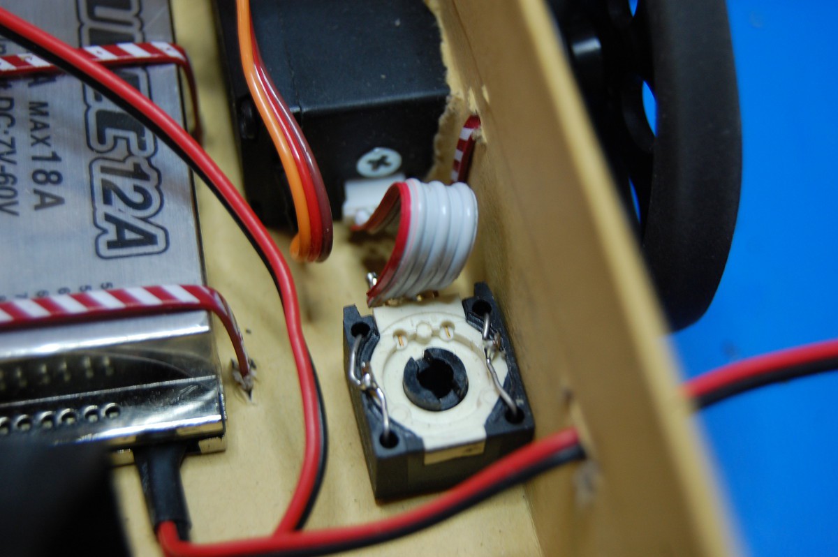
Now, since NeuroBytes are all a bit different (v0.4 uses the ATtiny44A's internal RC oscillator, so the 1-2 mS servo pulses aren't identical between Motor NeuroBytes boards), it's time to adjust the CR servo zero points. In the previous post, I turned around the servos so that the zero adjust pots were more accessible. This was still a pain (I kept pushing the board-mounted trimpots back), so I decided to mount external adjustment pots. Side project!
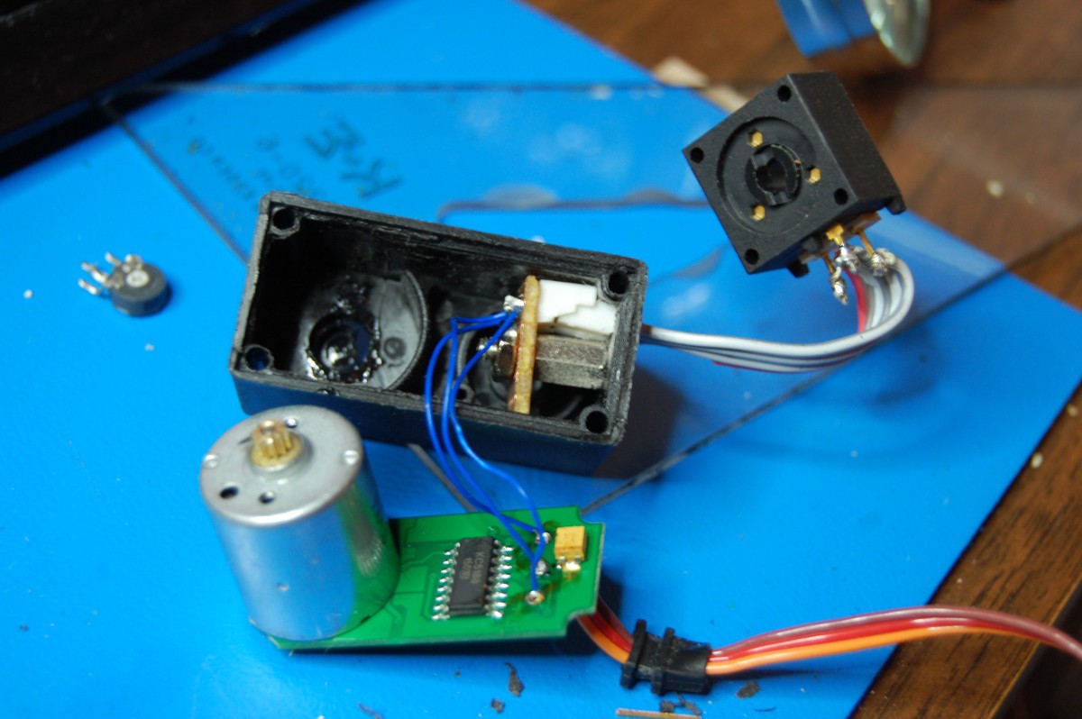
As you can see above, this got a bit more complicated. I used a standoff and a small piece of perfboard to mount a standard NeuroBytes connector in the servo case; this required a ton of trimming to clear the servo assembly screw post (which it barely does). Why the trouble? Well, the servos need to slide through a fairly tight rectangular hole in NeuroBuggy's chassis, and I didn't want permanently attached wires getting in the way. Also, the pots I happened to have around (which were 50k vs the 5k board-mounted unit shown in the picture above) were a bit big for internal mounting.
Once I tested the servo sans gearbox, I buttoned it up:
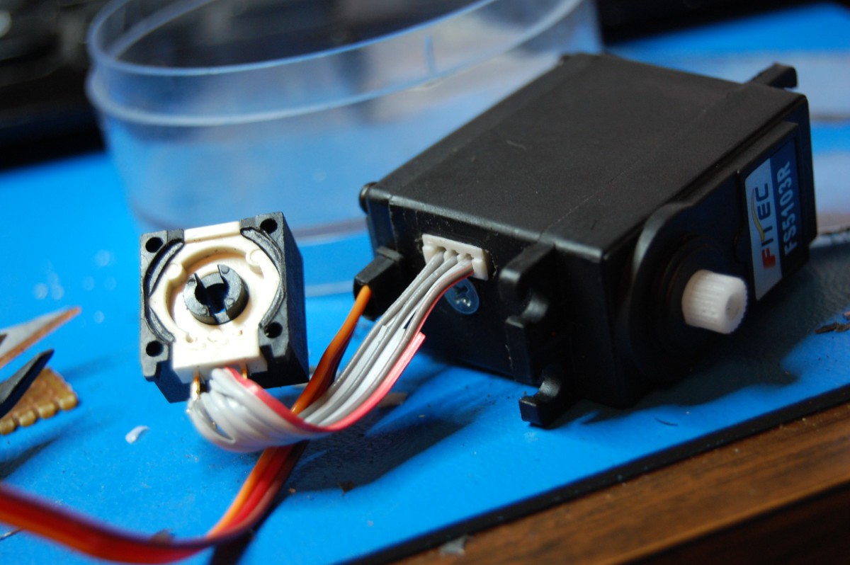
... pulled the pot out, installed the servo in NeuroBuggy, reattached and finally mounted the pot in the chassis:
I made sure to carve a decent size hole in the chassis so the zero points were still adjustable:
[note: at some point I acquired a large quantity of 1/4 watt 160 ohm resistors that I have since never used. As such, when you see them in projects (like the four here) they're generally used for holding things together.]
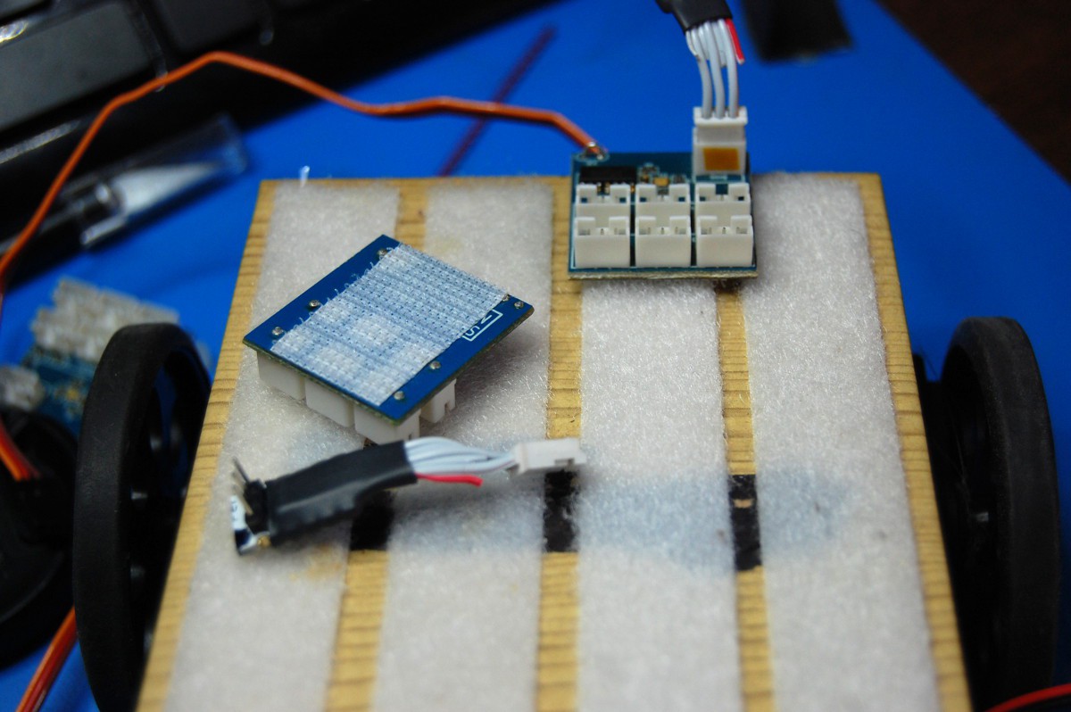
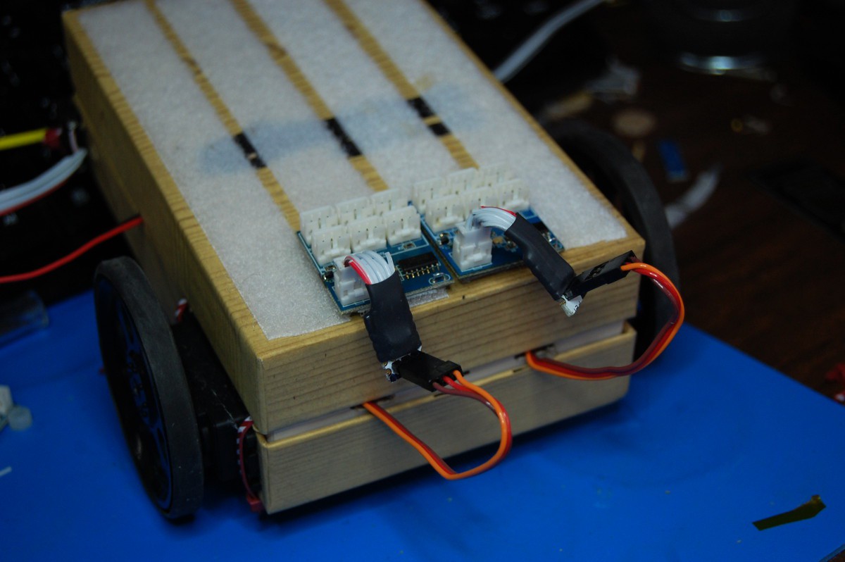
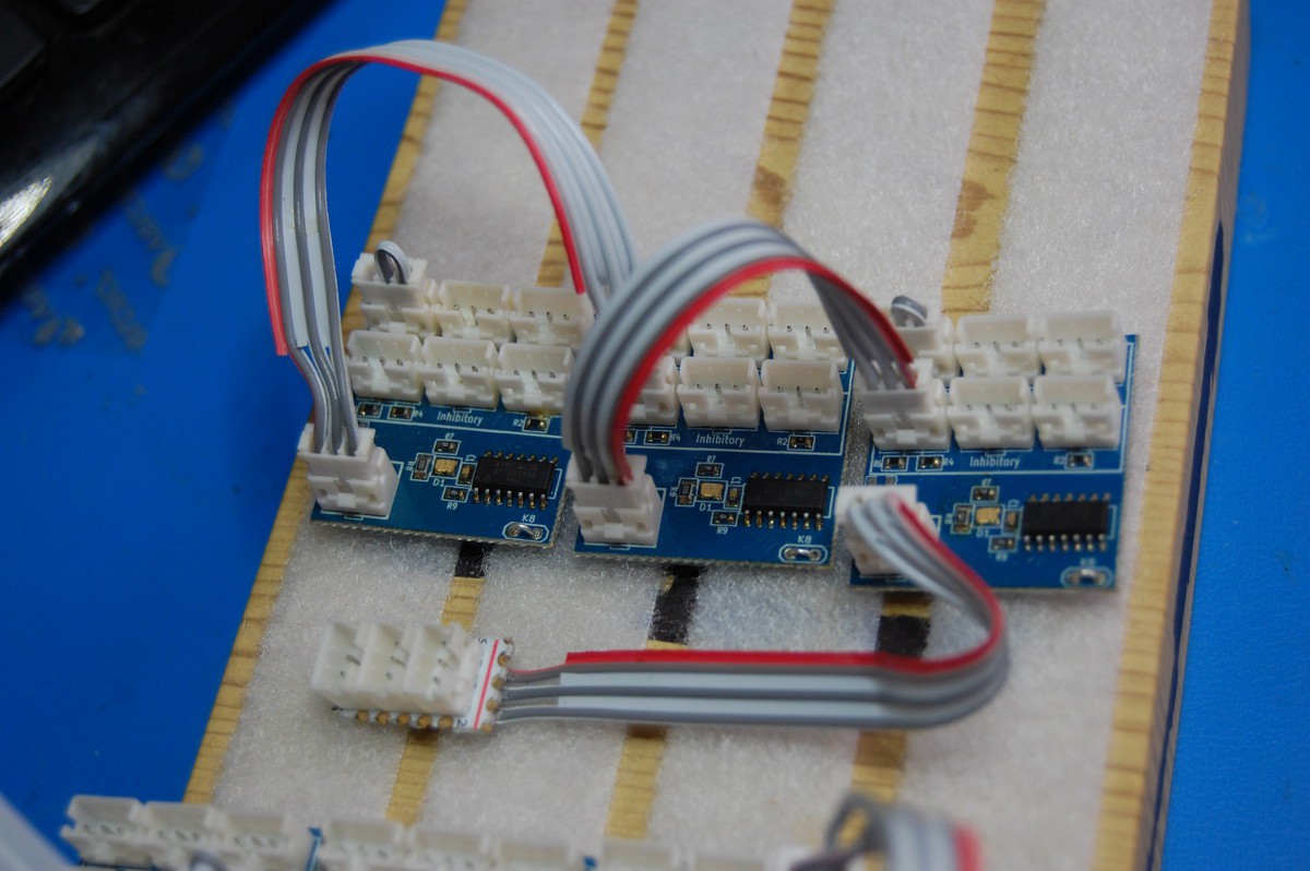
Okay, back to putting NeuroBuggy together. Next, it's time to mount the two NeuroBytes that feed directly into the Motor NeuroBytes:
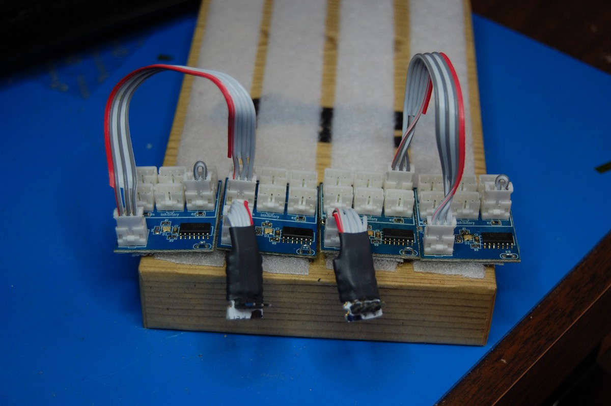
To keep the images clear, I've temporarily removed NeuroBuggy's brain from its chassis. Notice that the axons on each of the NeuroBytes feed directly into the Motor NeuroBytes (opposite inputs in this case; this picture was prior to splitting the Motor NeuroBytes into CW and CCW versions). The two new NeuroBytes also have Exciters installed, so they'll fire an action potential if they see a single excitation.
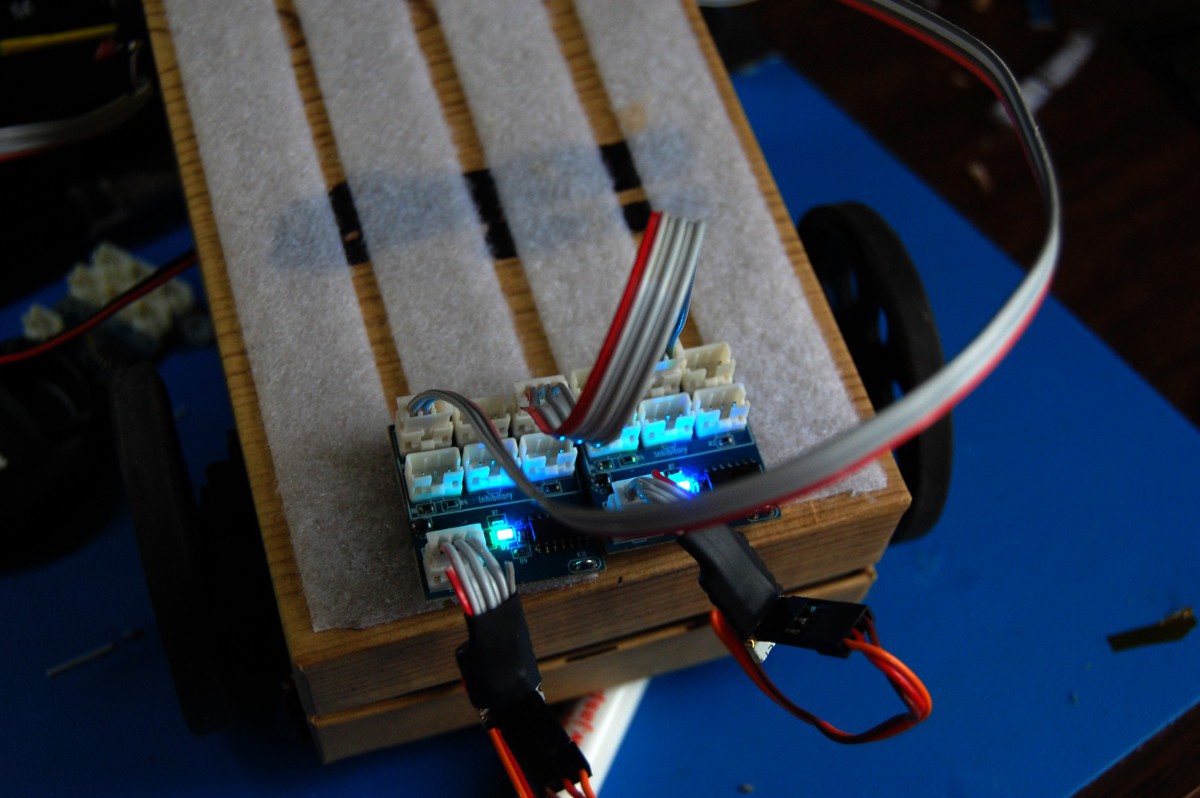
Next, it's time to build out the 3-element CPG:
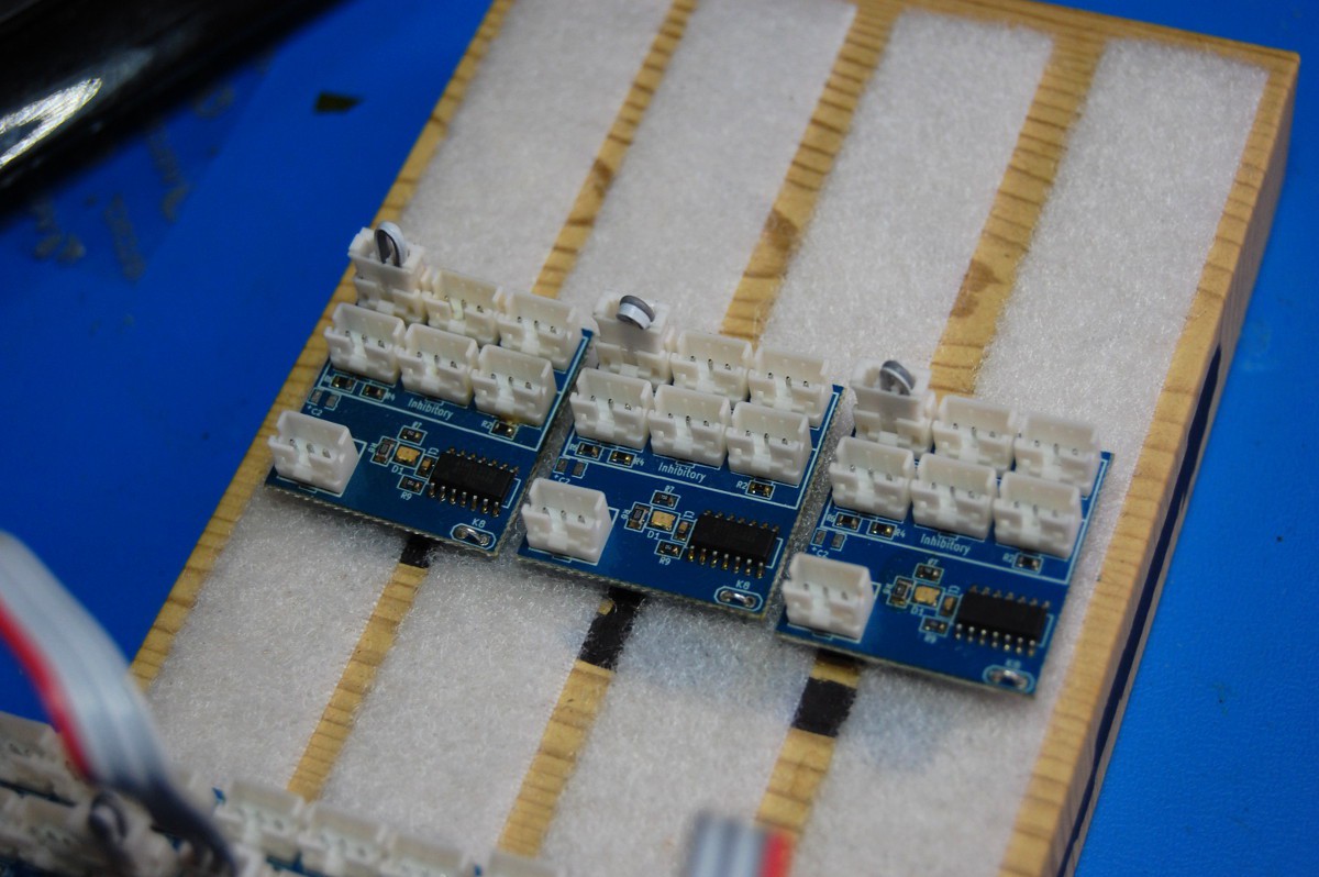
Again, these three NeuroBytes already have Exciters installed, so they'll trigger upon receiving a single excitatory pulse.
The CPG gets wired sequentially, with the last NeuroBytes board getting fed into an Axon Terminal:
This Axon Terminal then feeds back to the first CPG NeuroBytes board, along with both of the NeuroBytes that feed into the Motor NeuroBytes (and then the servos):

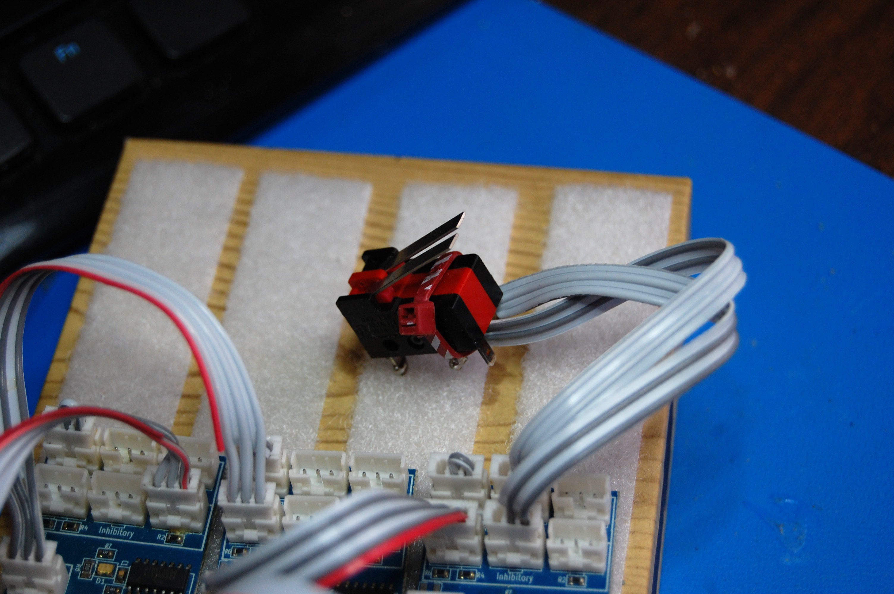
The START/STOP switch gets installed:
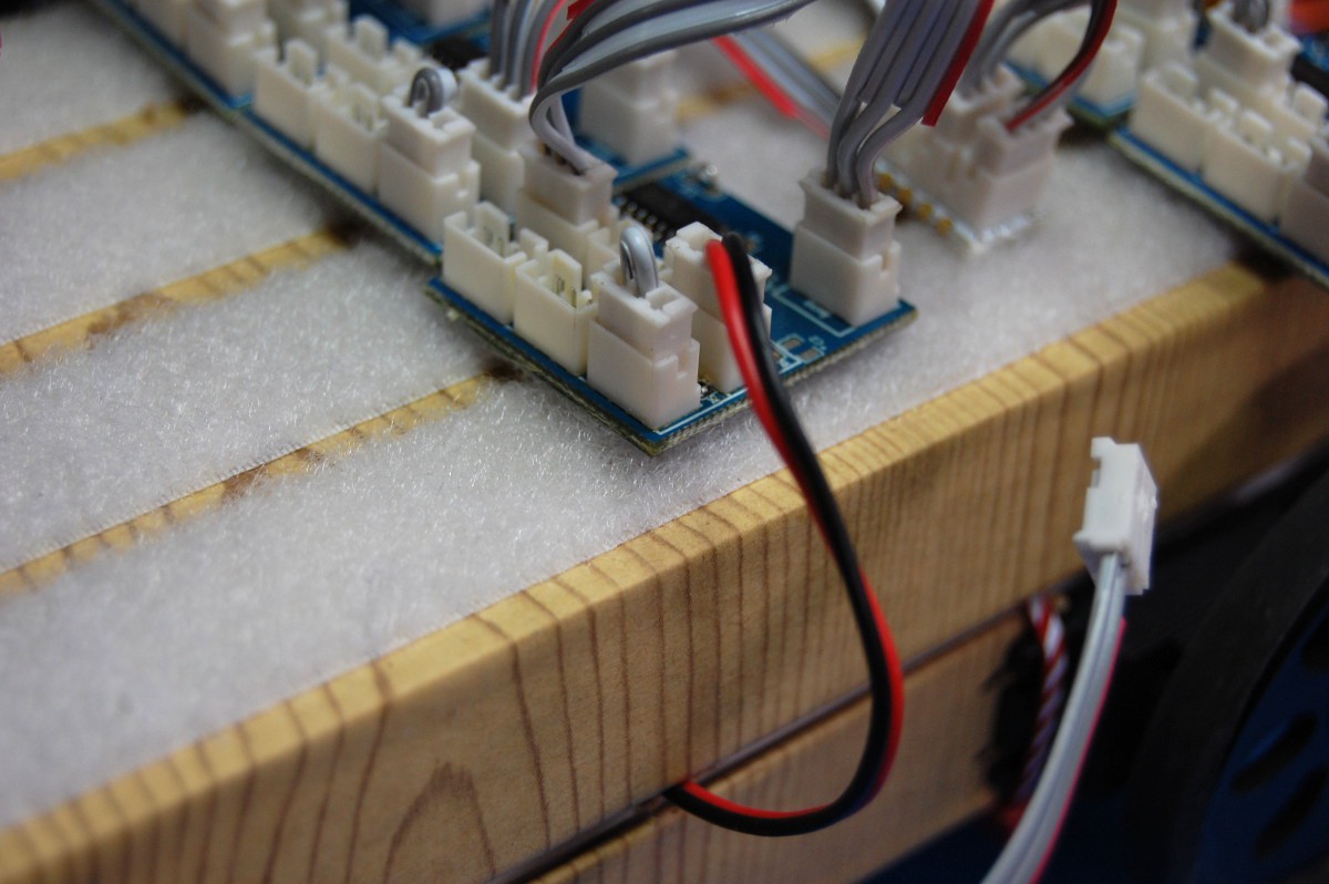
... and then the lid gets placed back on the chassis. This allows us to land the power and servo cables:
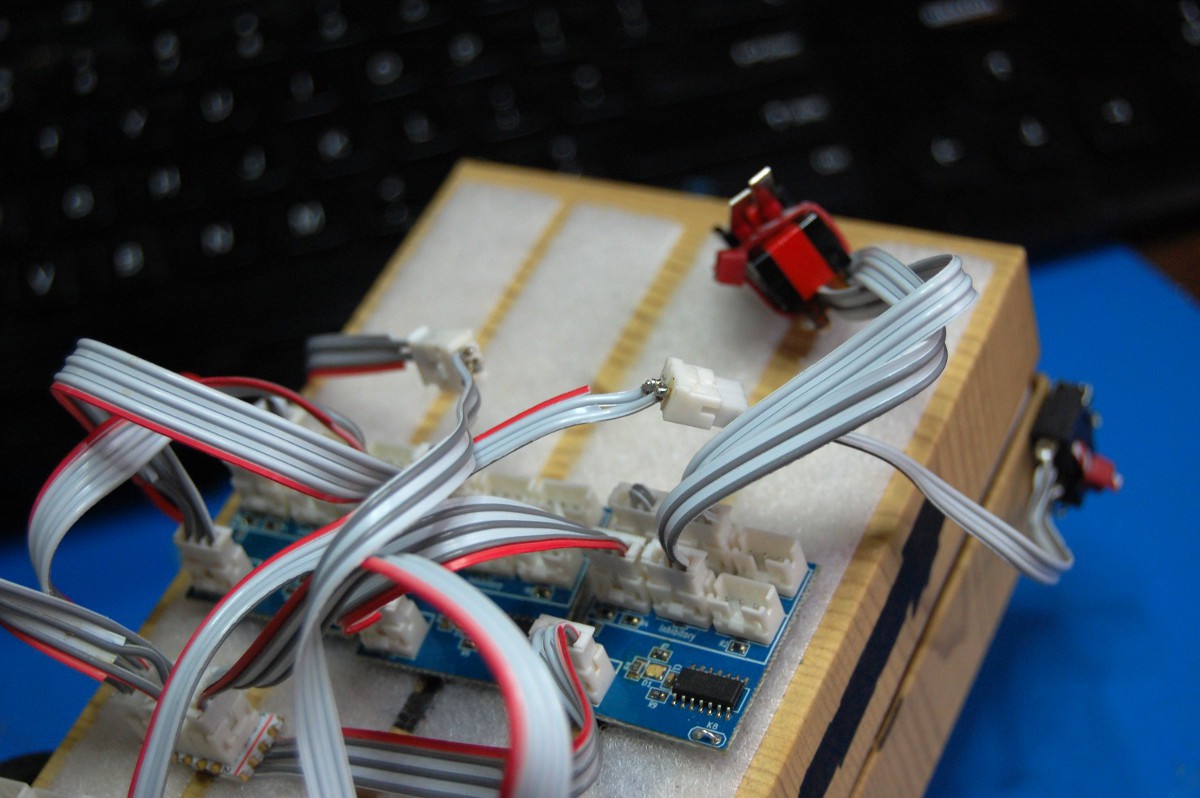
Finally, the two bump switches are fed (using extension cables) into the inhibitory/reverse rotation inputs in the Motor NeuroBytes modules (not shown in this poorly framed shot):
... AND WE'RE GOOD TO GO:

In case you missed the video, here it is again:
Simple, right? Don't worry--things can get a lot more complex, but that's for a different day:

Discussions
Become a Hackaday.io Member
Create an account to leave a comment. Already have an account? Log In.