 zakqwy
The JST GH connector has served me well since its initial selection during the development of NeuroBytes v0.8. Prior to choosing this connector, we ran a few usability tests with customers to see which designs were intuitive to use (some pigtails have been lost to history):
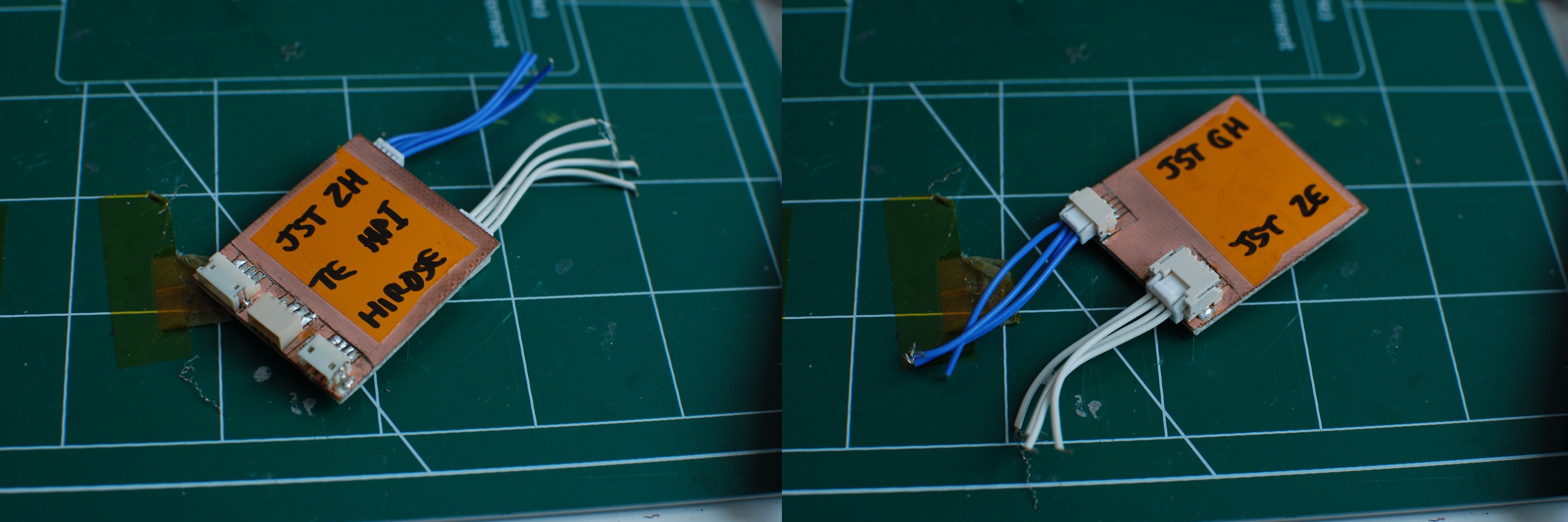
The GH was the clear winner; its locking tab was easy to understand and simple to operate, and the connector's small width compared to some competitors was a bonus during the PCB design. Definitely better than the tiny SH series used in v0.5, v0.6, and v0.7.
However, larger concerns loomed on the horizon. The JST GH datasheet omits connector lifetime: the closest the document offers is 'initial contact resistance' (< 0.030 ohms) and 'contact resistance after environmental tests' (< 0.050 ohms). These connectors, as with nearly every other PCB-mounted header, aren't designed to be consumer-facing, like a micro USB or 1/8" phono plug. Rather, they are designed for single use during assembly, and perhaps subsequent use during hardware upgrades or repairs.
To date, we have built roughly 700 NeuroBytes boards that use the GH platform, and we have never observed an issue stemming from connector aging. Voltage drop across large networks is essentially negligible, and the additional 1 V headroom provided by the on-board LDO allows us to tolerate higher neuron-to-neuron contact resistance. On the flip side, a number of highly qualified individuals -- JST factory engineers, sales reps, independent electrical engineers, and others -- have raised valid concerns about connector aging, particularly as the failure mode would likely be quite frustrating to end users. No one likes intermittent connections.
Time for some instrumented tests.
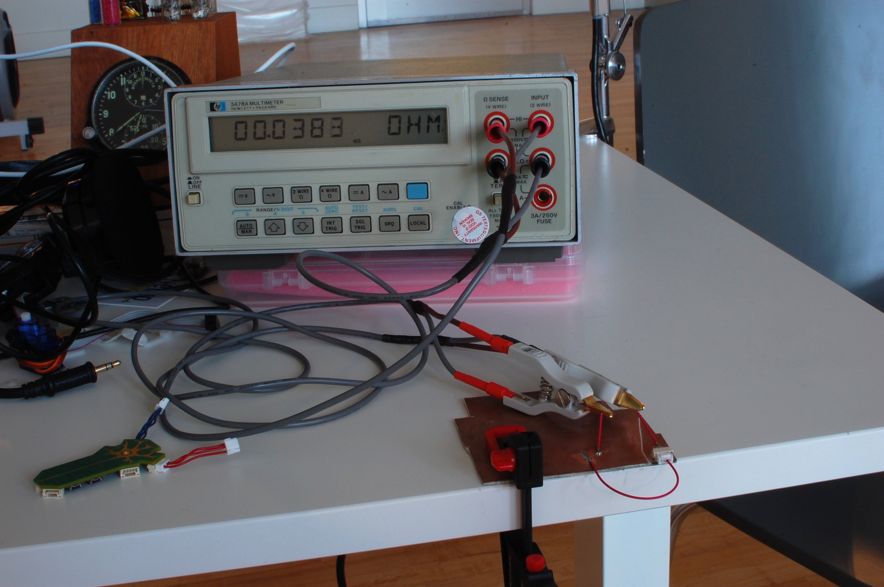
Finally an excuse to eBay a four-wire resistance meter! The HP 3478A isn't the newest bit of kit, but this one seems to work well enough (although it is not calibrated). I also picked up a set of unbranded Kelvin clips and a Prologix GPIB-USB adapter. Using the ++read command and gtkterm, I can now continuously log the meter reading to a text file. No time stamps, but it sure beats manual data entry.
The test setup, shown above, is simple enough: I soldered an unused JST GH header to a slab of FR4 and assembled a matching connector which I also soldered down via a short pigtail. Then, I attached two additional leads for the Kelvin clips. The FR4 is clamped down, meaning the entire setup doesn't physically move during testing. It's not perfect -- the milliohm measurement includes the resistance of a bit of FR4, four solder joints, and ~20cm of wire -- but it's good enough to see how the contact resistance changes over time.
Next, I turned on a few Youtube teardown videos and manually cycled the connector 2,322 times. Each time I mated up the header, I left it connected long enough to get a handful of readings; during the data analysis, I dumped the first reading (it ranged from 10x to 1000x the stabilized measurement) and averaged the rest for each point:
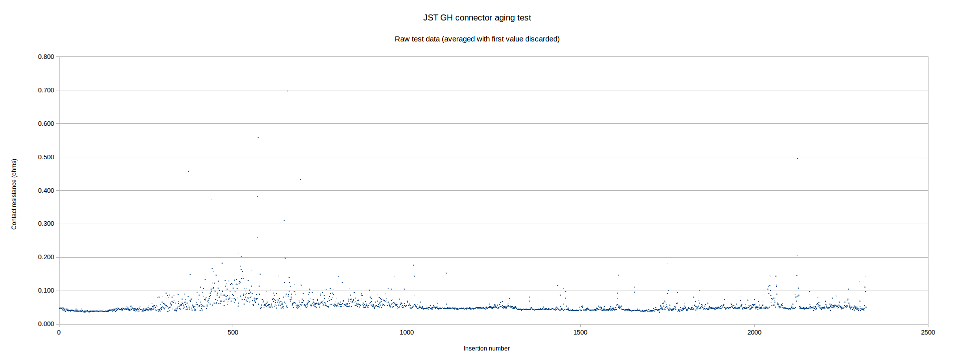
[click the graph to see a larger image -- you'll likely have trouble reading the axes inline... ]
As you can see, the connector resistance is quite consistent for the first few hundred cycles -- roughly 40 milliohms. Near insertion 300, the resistance variability starts to increase, although in the vast majority of cases it still remains below 100 milliohms. Subsequently, the measurement stabilizes again and stays fairly constant for the remainder of the test.
When I fitted a line to the data, the slope was almost exactly zero -- a great sign, as it suggests the connector contact resistance isn't gradually increasing. Additionally, the variability seemed to stabilize halfway through test. In order to better quantify this variability, I put together a histogram of the data:
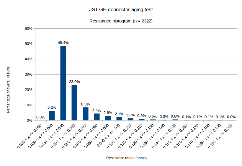
As you can see, measurements over 100 milliohms aren't common. The data is also skewed away from normalcy -- the median value is 0.049 ohms, while the mean is 0.057 ohms.
It's worth mentioning here that the real-world impact of contact resistance depends on a few factors -- specifically, the current draw of each NeuroBytes board, and the total length of the chain. If we make a few conservative assumptions:
- maximum chain between a NeuroBytes board and a power supply is 10 connections.
- individual contact resistance equal to values tested (i.e., each NB --> NB connection is 4x the recorded value: two ends and two power conductors per cable).
- average current draw per NeuroBytes board is 30 mA.
Using 0.05 ohms as the resistance value per connector, the chain can be modeled as follows:
Obviously servos can cause complications here; I've measured up to 750 mA for a stalled 9g servo, which would produce an additional 0.15 V drop per link. Yet another reason to consider local servo power supplies, I suppose.
Comments/suggestions/etc welcome. Once I'm satisfied this issue is put to bed I likely won't address it again for some time, so speak now if you think my test methodology or model could use some work!
Discussions
Become a Hackaday.io Member
Create an account to leave a comment. Already have an account? Log In.