 zakqwy
We're on the other side of our two trials--UW-W and PHHS--and by all accounts they were fantastic. We did a pre- and post-test for each session to try to gauge learning gains, and included a large section for free form comments. Data is still getting crunched, but the comments were overwhelmingly positive, especially from the high school crew. Success!
One significant learning, however, was that microcontroller brownouts caused by hot-swapping the servos were pretty frustrating. The students thought it was a bit funny that the solution was to cycle the power ("omg that actually works!"), but the condition is clearly not acceptable for a final product.
Above: Re-inserting the servo connector causes the LED to extinguish, go into bizarre super-bright mode, and then reset to the normal state. Not a good sign.
I ran the power lead through a 0.1 ohm shunt and plotted current (channel 1) and bus voltage (channel 2) at the moment of connection:
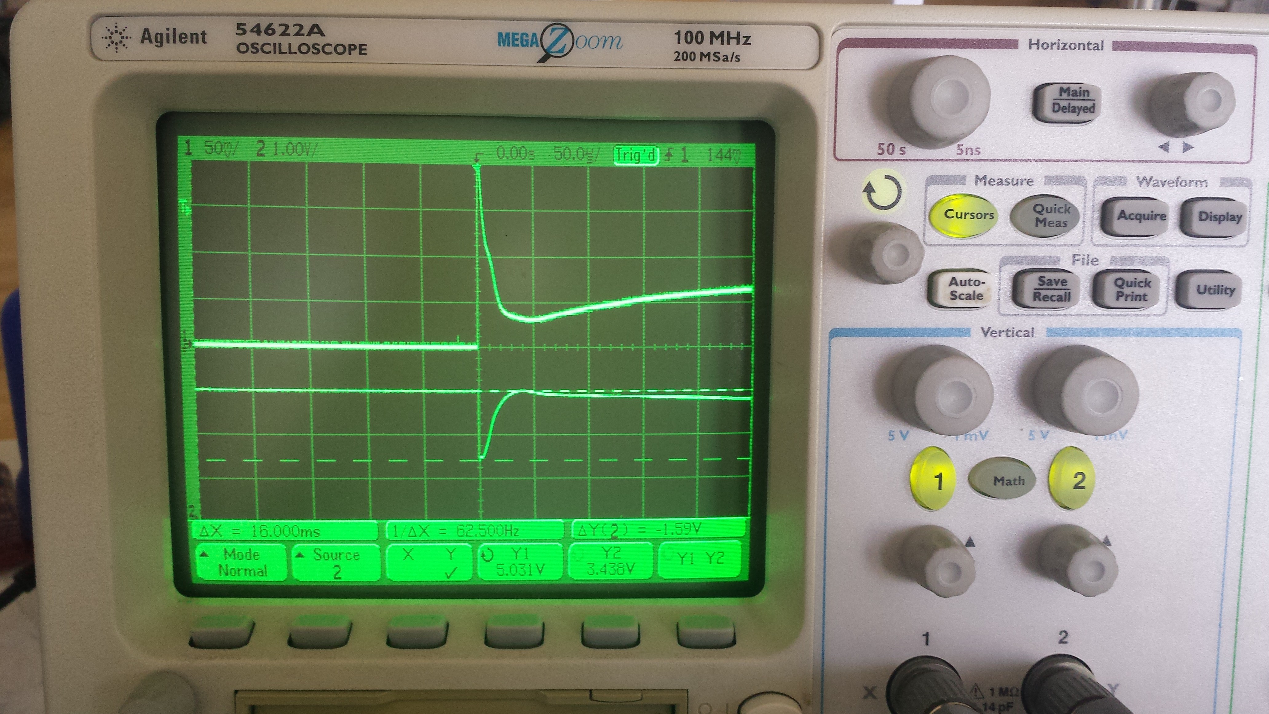
Above: The current draw spike and corresponding voltage bus sag caused by connecting a servo. The voltage rail typically dips to 3.5 VDC or so, easily sufficient to brownout the ATtiny88.
Using Dave's excellent lexicon, the hacky solution would be to 'whack a bunch of capacitors on the output'. Before doing this, I wanted to quantify the amount of capacitance really needed to absorb the complete servo power-up demand. Starting with the basic equation, where C is capacitance in Farads and q is charge in coulombs:
Charge is the total current flow integrated over the time period in question:
So. I believe this means that I can integrate the current curve over time, then divide by the maximum acceptable voltage drop--say, 0.5 VDC--to get a reasonable first pass at the total ideal capacitor value I'd need to minimize voltage rail sag. The 'scope has an integration math function, and integrating the current trace until it falls back to near zero (which takes a good bit longer than the screenshot above suggests) yielded 21.9 mA*s, so...
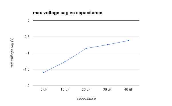
Calling my EE knowledge rusty would be an understatement, so any comments are appreciated here. In any case, I ran a few tests with a bunch of different caps and found the above value to work using a bunch of parallel aluminum electrolytics I had lying around (all values averaged over five tests):
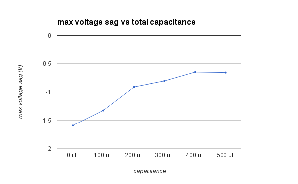
So... close, but not quite 0.5 volts. And yes, I did try ganging more capacitors together but still hit a wall at ~0.6V sag:
For what it's worth the microcontroller never browned out under these conditions, but I wanted to avoid using a ton of big electrolytic capacitors if possible. I took a look at littleBits' open-source servo adapter schematic, assuming they're interested in enabling hot-swapping too, and noticed a 47 uF polarized capacitor across the servo terminals. I also located a Youtube video that showed the back of the adapter and noticed that it was a tantalum unit, presumably for longer life and lower ESR. Looks like they're less worried about the entire length of the sag and more concerned about the initial spike... interesting!
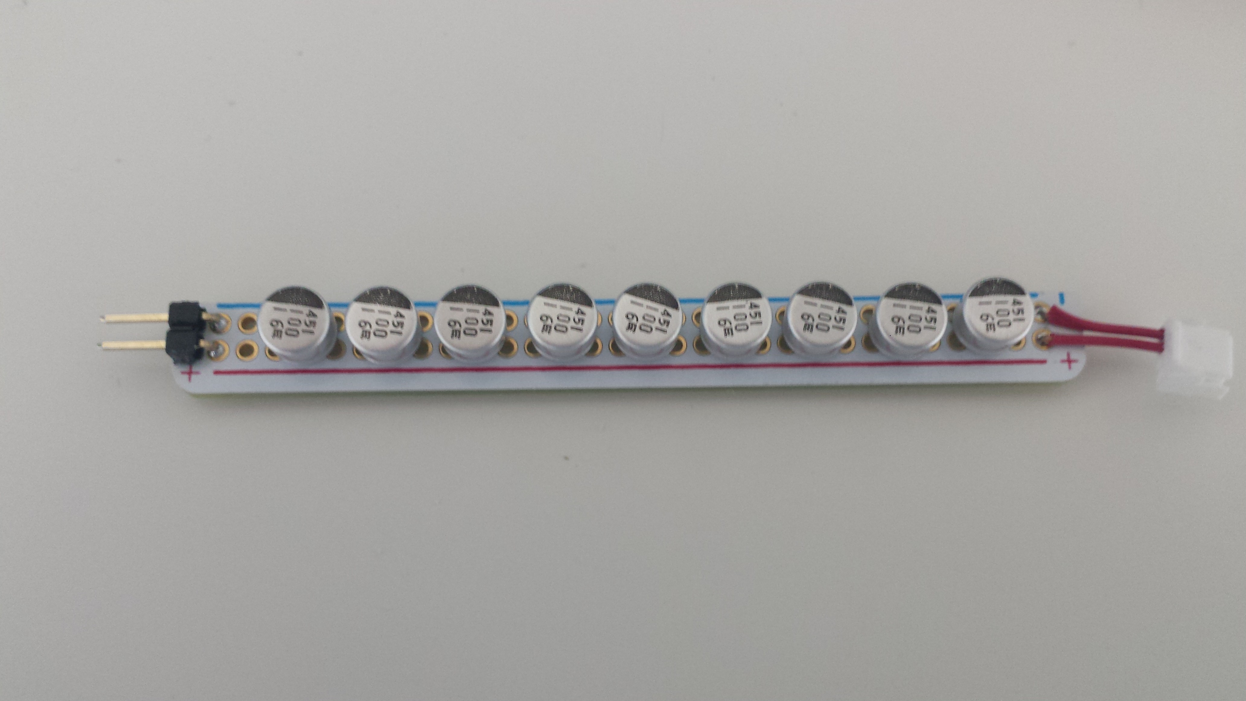
More testing. I didn't have any 47 uF tantalum caps, but I did have a bunch of 10 uF units that I started paralleling together to see how they'd effect the circuit:
[Sharp eyes will notice that I desoldered the 10 uF tantalum unit from the NeuroBytes board for testing...]
Results were promising:
I didn't plot beyond four parallel capacitors, but I did test the NeuroBytes board with nine just to see what would happen; the ridiculously low ESR of the cap bank allowed the servo to draw an instantaneous current of 6 amps on startup!
Okay, great! Problem is solved. Only it isn't... I don't want to add a 47 uF tantalum capacitor to each NeuroBytes board. Why? Well.. look what happens when I plug in the 90 uF bank, instead of leaving it connected and hot-swapping the servo:
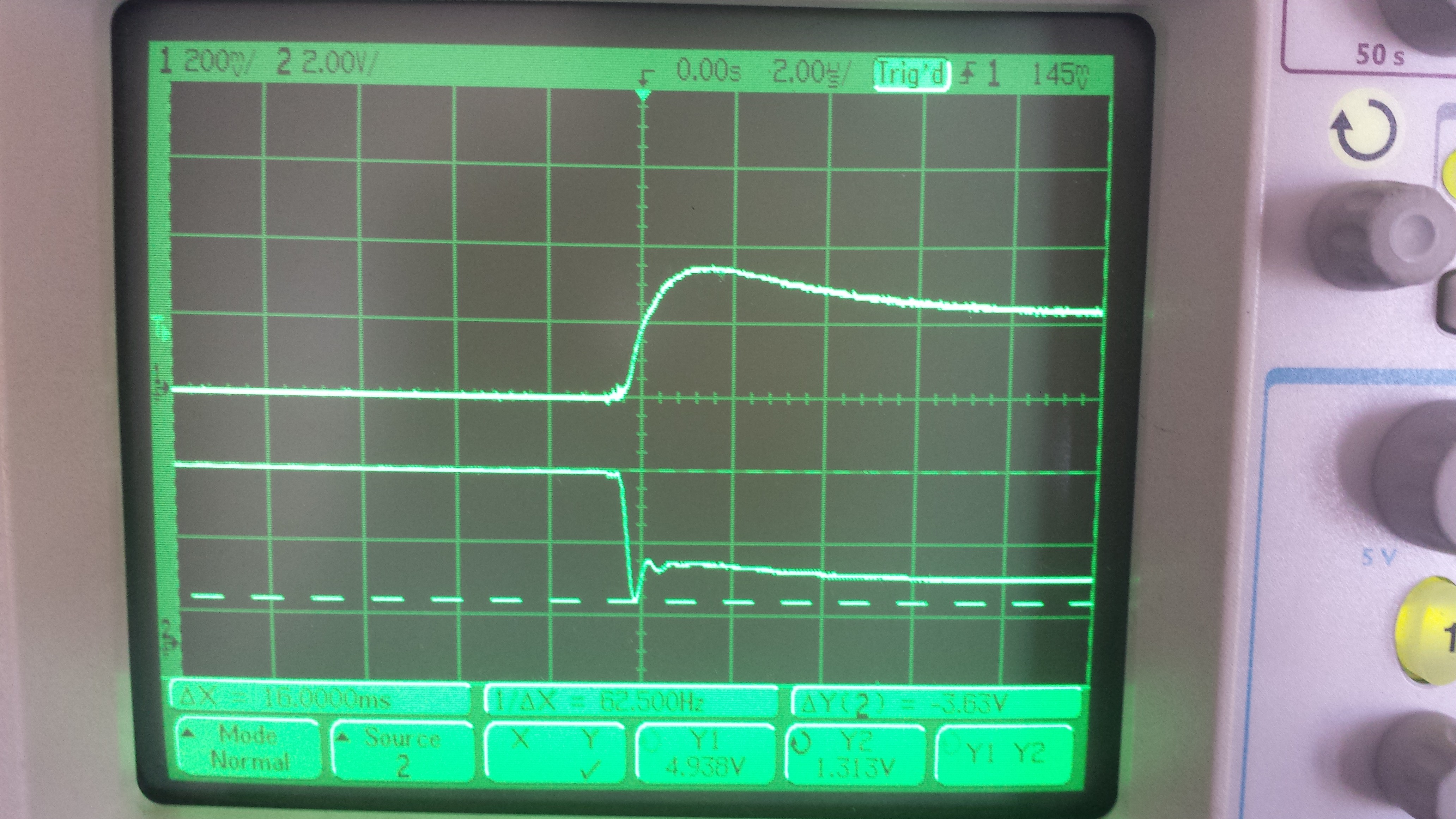
Note the revised scale for channel 2; if you can't read the cursor at the bottom, it shows the voltage rail sagging to 1.3 volts for a few hundred nanoseconds, then staying below 2.5 volts for the rest of the screen. As expected, the microcontroller didn't like this!
Here's the issue: if I put such a capacitor on each NeuroBytes board, there's a chance that connecting new boards will cause upstream boards to reset by sagging the power rail while their reservoir caps charge. This basically pushes the problem upstream--once the boards are all powered one could hot-swap the servo (as the charged cap would handle the sag), but new boards would cause resets! It's super frustrating when you build a big neural circuit and suddenly LEDs start doing weird stuff.
So I decided to make some modifications to the servo adapter. Moving the reservoir cap downstream saves me $0.12 per board; since servo adapters are less common than NeuroBytes, I can afford to make the adapter a bit more complex without increasing the overall COGS of a complete kit. Here's what the circuit needs to do:
- Directly connect a large reservoir capacitor (likely a 47 uF tantalum unit) across the servo power terminals.
- Charge said capacitor slowly enough to avoid sagging the power rail beyond -0.5 (or -0.6) volts, even with a somewhat limited power supply.
- Provide as much current as possible to the servo once it's running so it stays happy and torque-y.
The first goal has already been accomplished. For the second, I can simply connect a decently sized resistor in series between the upstream NeuroBytes and the reservoir capacitor to limit its charge rate. But what happens when the capacitor is charged? Now that resistor significantly limits the amount of current the servo can pull from the power rail! Not good.
Here's what I came up with:
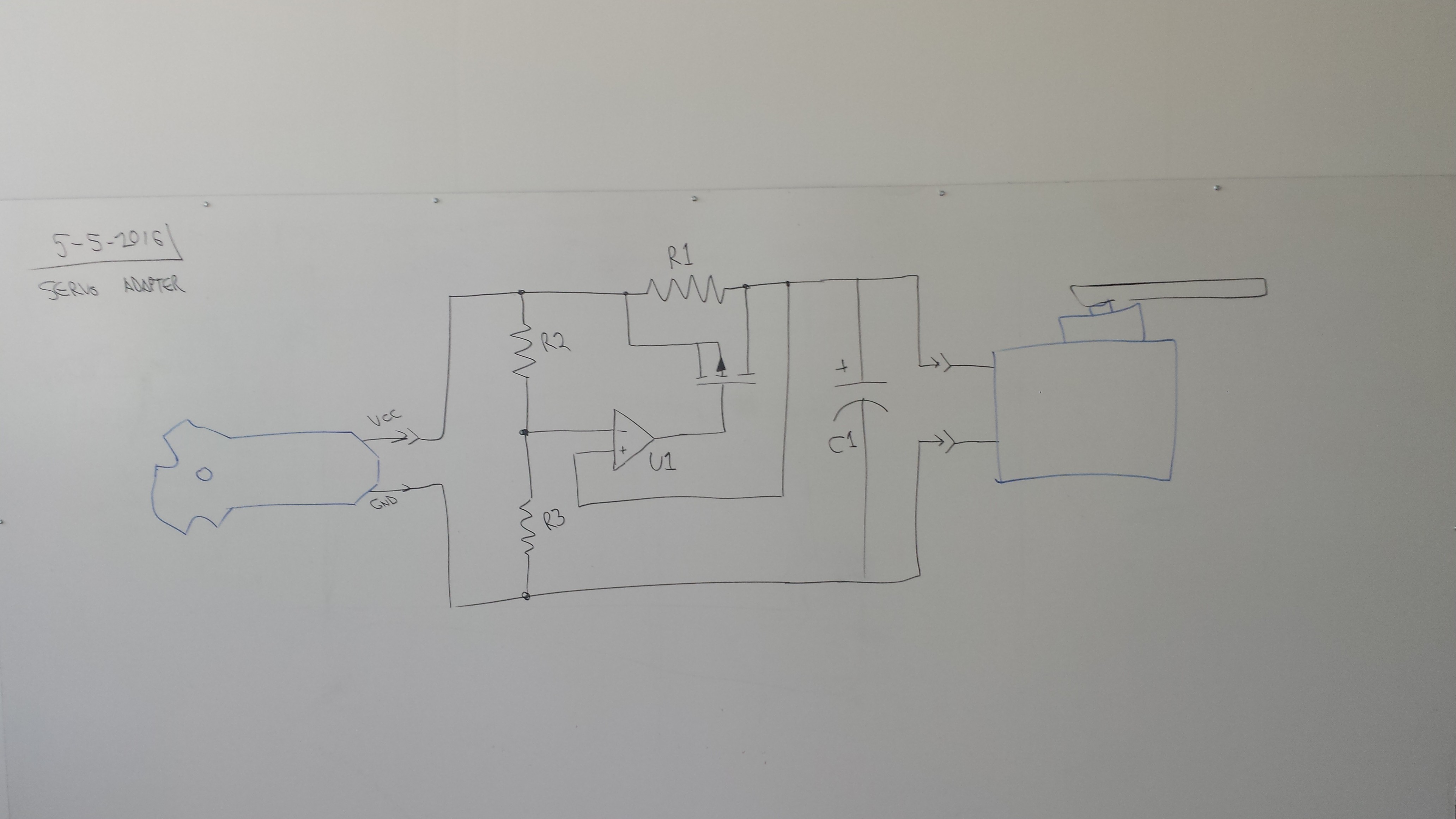
The comparator, U1, compares the voltage downstream of R1 to a midpoint set by R2 and R3. It switches on when the voltage drop across the resistor decreases sufficiently, indicating that the capacitor is almost fully charged and the current flowing into it has been reduced to the point that it will not produce an inordinate sag on the power rail. When the comparator does switch on, it charges the gate of the P-channel MOSFET Q1 (I forgot to label this one) which then provides a low-resistance bypass around R1 so the servo is no longer significantly current-limited. The circuit should stay latched once the capacitor is charged, since the MOSFET will expose the positive comparator input to full rail voltage; even if it sags a bit when the servo actuates, the negative input should sag more due to the R2/R3 voltage divider.
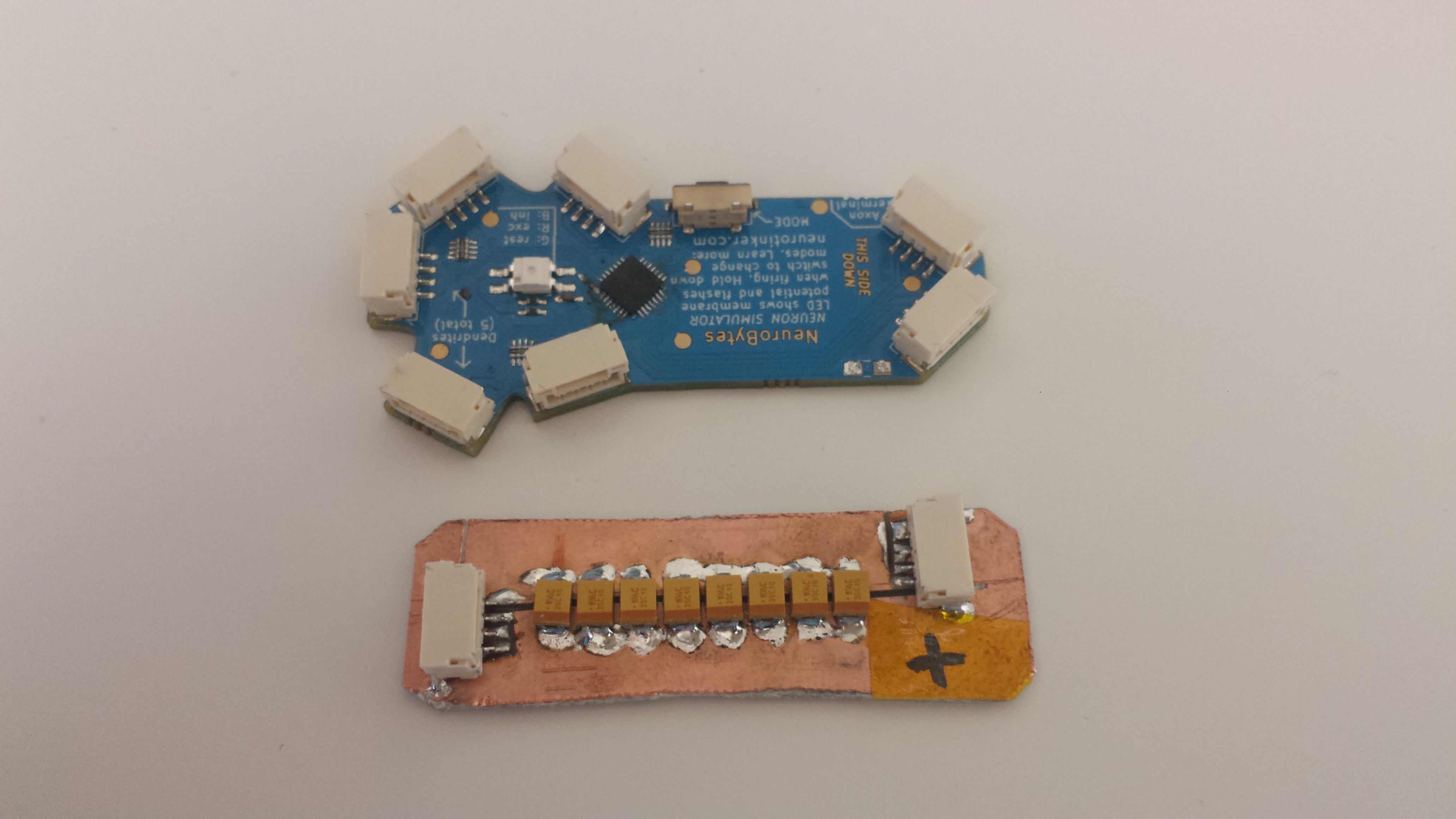
I didn't have a P-channel MOSFET lying around or a dedicated comparator for that matter, but I did have a strip of somewhat overkill op-amps that would work for a quick prototype of the sensing portion of the circuit:
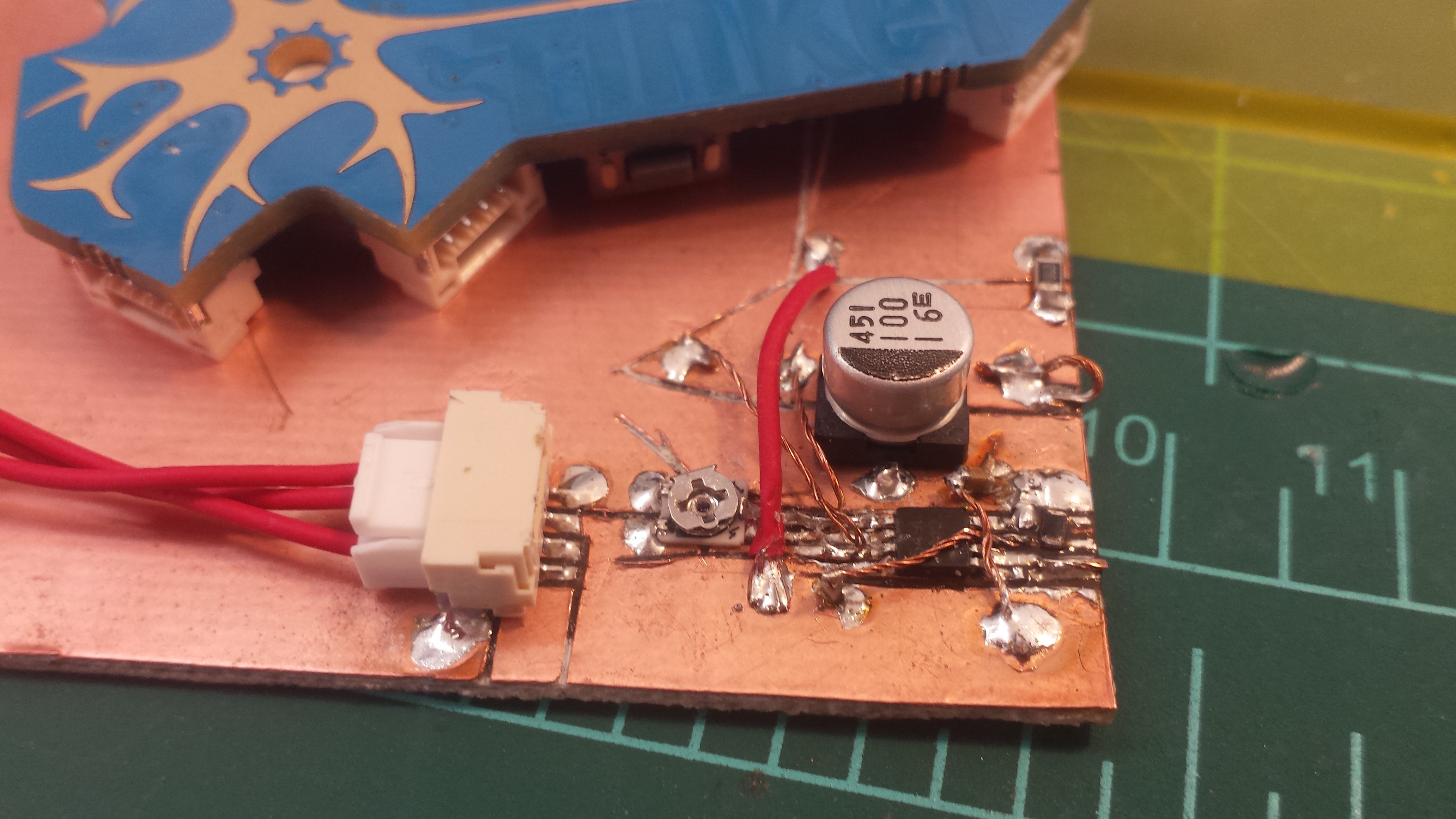
[note the 10k variable resistor--I wanted to putz with different voltage divider settings--along with the non-tantalum reservoir cap, since it's what I had around. Also, my tombstoned 0.1 uF filter cap fell over but still worked well enough... and yes, I ran out of IPA so this is not de-fluxed!]
I 'scoped the capacitor charging voltage and the comparator output; the circuit seems to work, as tweaking the variable resistor caused the output to move relative to the capacitor charge initiation:
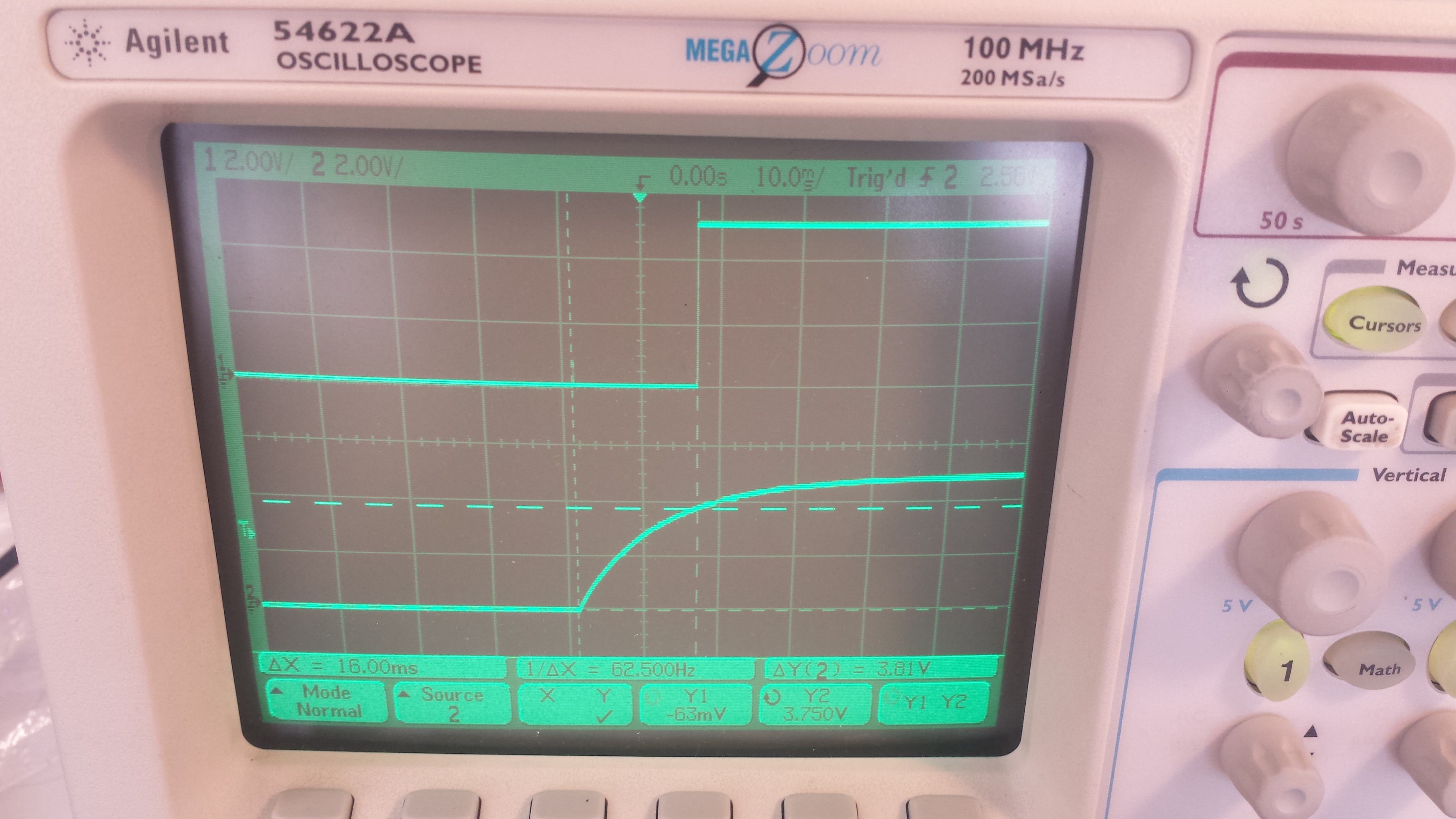
[here, the comparator flips on 16 ms after the capacitor starts charging, when the voltage downstream of the current limiting resistor hits 3.75 volts. The resistor value is 1k, since it's what I had lying around...]
I ended the day yesterday by ordering a handful of cheap-o comparators and P-channel MOSFETs that seem to fit the bill (reasonably high current handling capacity, etc). I'll toss up another log once I've tested the full circuit.
SO. Comments? Suggestions? This is the first analog circuit I've ever really designed (/bodged together), so I'd love to hear your thoughts! Am I making this whole thing waaaaaaaaay to complicated?
Discussions
Become a Hackaday.io Member
Create an account to leave a comment. Already have an account? Log In.
The absolutely beautiful thing about servos is that they don't need to be on the same power supply as the logic at all! (Just make sure they share ground.)
When I build small bots, I usually have two sets of batteries, one for motors and one for logic/sensors. This keeps motor noise out of the logic power supply, and makes it very easy to run your motors at a higher voltage without any confusion.
I've even gone with rechargeables for the motors and regular batteries for the logic, b/c it drains so much slower. And then I got a lot of rechargeables and use them for everything. :)
Are you sure? yes | no
Separate power supplies would definitely be ideal; unfortunately, that introduces some usability challenges that I'd like to avoid. Most of the kits we have planned will use one or more servos, and I'd rather avoid having to supply customers with two power sources (along with all the instructions required to make sure they keep 'em isolated). A unified power architecture really cuts down on the tedium of assembling and troubleshooting neural circuits.
Likewise on requiring NiMH batteries; I'm trying to keep the power supply side as simple as possible, meaning it should work with any old AA batteries.
Thanks for the suggestions! I'm building all of the suggestions here (along with some excellent bits of info from offline conversations) into the v09 design so I can do some real-world tests and see what works reliably.
Are you sure? yes | no
You can isolate the power supply by using a Schottky diode in series for the microcontroller and add capacitor after the diode. When there is a sag, the cap holds some charge for the microcontroller. The diode blocks the current from the cap going to the servo side during a sag.
This is a cure for the symptom, not the cause. The cause is the power supply not rated for the inrush So either controlling the inrush or have a bigger supply.
There are USB power switch that does current limits. I used Diode Inc AP2511 It is rated for 2.5A. They have smaller currents too.
Are you sure? yes | no
Ah, that makes a lot of sense.. I'll give that a try. Schottky diodes are the ones with especially low voltage drops, right?
I'm changing the power scheme around a bit for v09; currently, all NeuroBytes (and servos) share a common 5VDC power supply from a 4xAA battery pack with a linear regulator, which might be causing a bottleneck as it's only rated for 1 amp. The new design uses an unregulated 6VDC power rail with individual on-board regulators for each microcontroller. Maybe that will help isolate the microcontroller from the servo supply?
Thanks for the suggestions!
Are you sure? yes | no
Schottky rectifier diodes would have a 0.2-0.3V drop when moderately loaded.
The servos can handle 6V, so you don't need a regulator. More likely is the regulator over current protection that cause the sag.
If you use NiMH (instead of AA) with good quality wiring/connector for the battery pack and that should improve the sag too. You should check the wiring if you are using cheap battery box from China.
Are you sure? yes | no
Not being an electrical engineer, I can't provide any feedback regarding whether this is a good approach or not. However I really enjoy how well you document your issues and your thought processes in solving the problem. At least it's solved and you can move on!
Are you sure? yes | no
thanks! Yeah, with any luck this puts the problem to bed. I've had a few suggestions to try low-value resistors in series with the servo, just to see if that tamps down the sag enough to work... K.I.S.S., that sorta thing. I'm going to keep fiddling, but I'll definitely build the circuit shown as an exercise regardless..
Are you sure? yes | no