 willbaden
To create more of a finalized installation, a Seeed Studio protoshield was purchased. This was populated with the minimal required circuits/connections. Here is the final proto board populated:
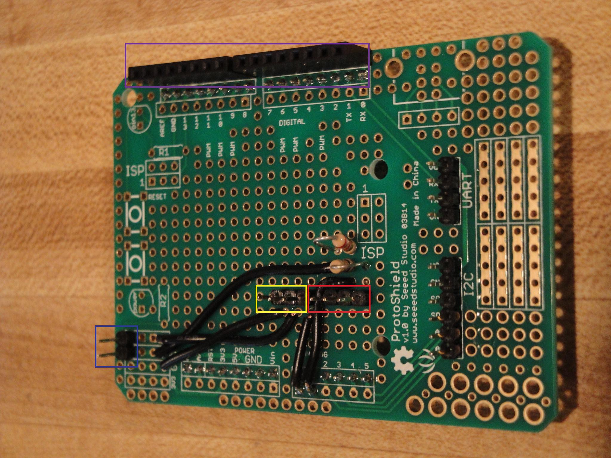
Analog 0 will read the Current sensor. The current sensor will connect to one of the 3 pin connectors (yellow rectangle). The voltage divider attaches to the second 3 pin connector (red rectangle) and uses the outside two pins for GND and the center pin for 12V. This GND is bonded to the ground of the 5V supply on the Arduino. There is also a 2 pin header that will feed 5V power to the relay board (blue rectangle). This feeds power to the control circuits of the relay board. The control outputs to the relay board will attach via 2 connectors (purple rectangle). Using outpus 2 - 8.
Discussions
Become a Hackaday.io Member
Create an account to leave a comment. Already have an account? Log In.