 suedbunker
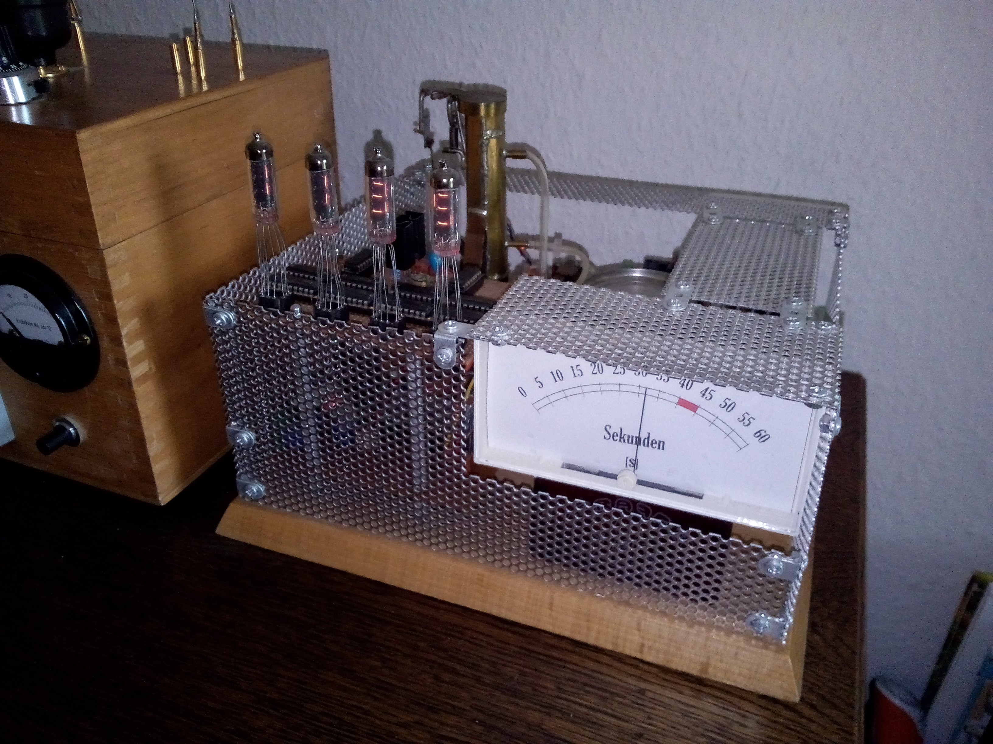
There are moments in the life of a tinker, hacker etc. when worlds are changing. One of these moments was my change from a basic based microcontroller to the big world of Arduino. I started the microcontroller programming around 1999 with the C-Control Unit from Conrad [ https://de.wikipedia.org/wiki/C-Control ], a German electronic distributor. A Motorola based microcontroller programmable with a visual programming language and also with a dialect of basic. This was my start. In this time I was thinking about building a new clock. I have built my first Nixie clock [ https://www.youtube.com/watch?v=nhuDD7Ie47c ] some month before and was infected by the idea to build directly another one, but not a Nixie. This was around 2011/12 and I decide to use this fancy Russian Numitron tubes. Simple filament vacuum tubes with eight “segments” made of tungsten wire. And this clock should be a bit different. There are many methods to remind the people what time it is like bells, electronic beeper, flashing lamps, vibration etc, but what about smelling the time? In addition to this I have build a lot of small steam punk boxes [ https://www.youtube.com/channel/UCzx2u1cLnMxc4V5s6bZg2zQ/videos?sort=dd&view=0&shelf_id=0 ] with different electronics, sensors, tubes and old displays and I want to build a “Steam Clock”.
Steam Clock YT link: https://www.youtube.com/watch?v=5RXw3Jb6DJg and wait for it!
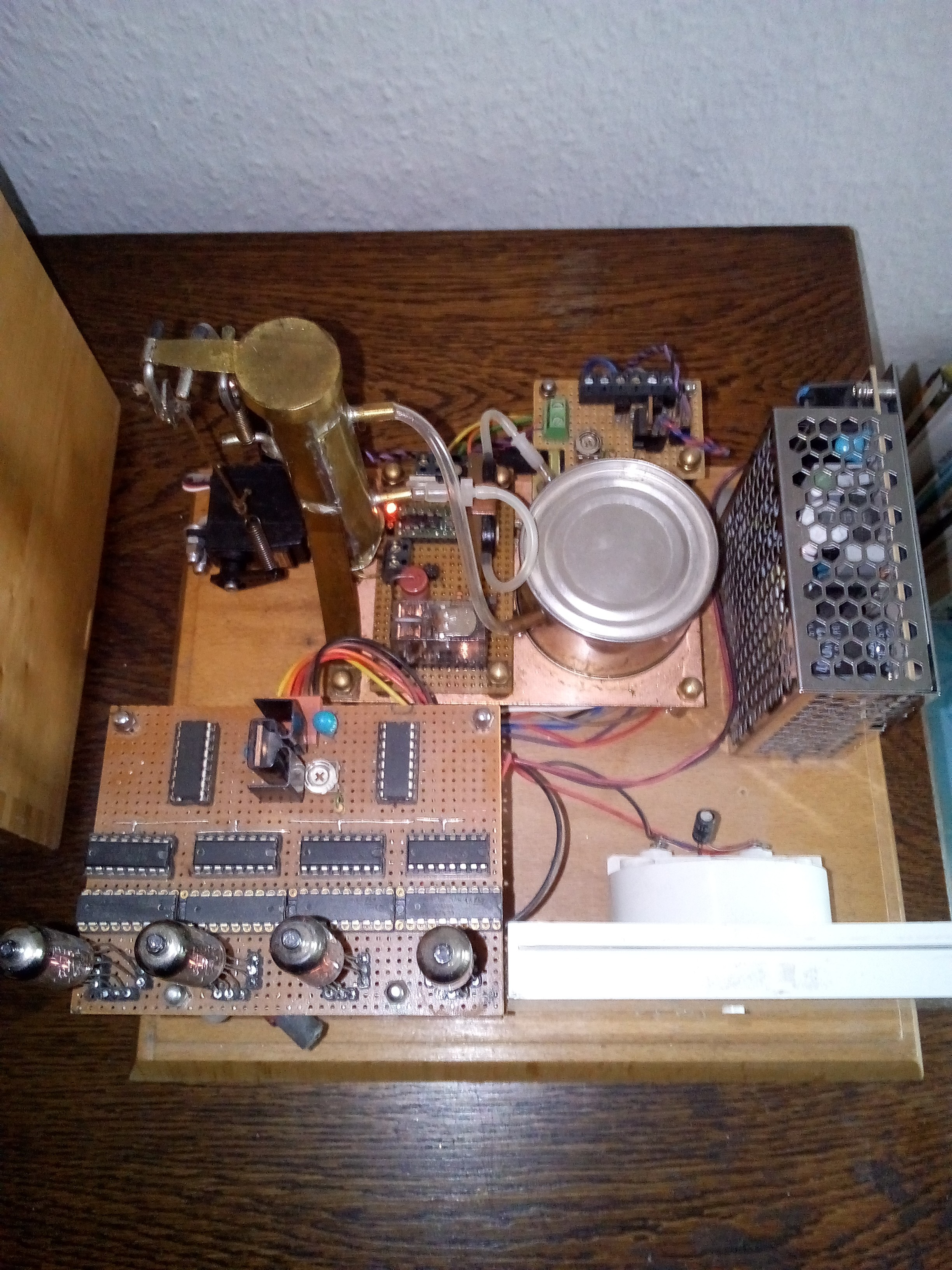
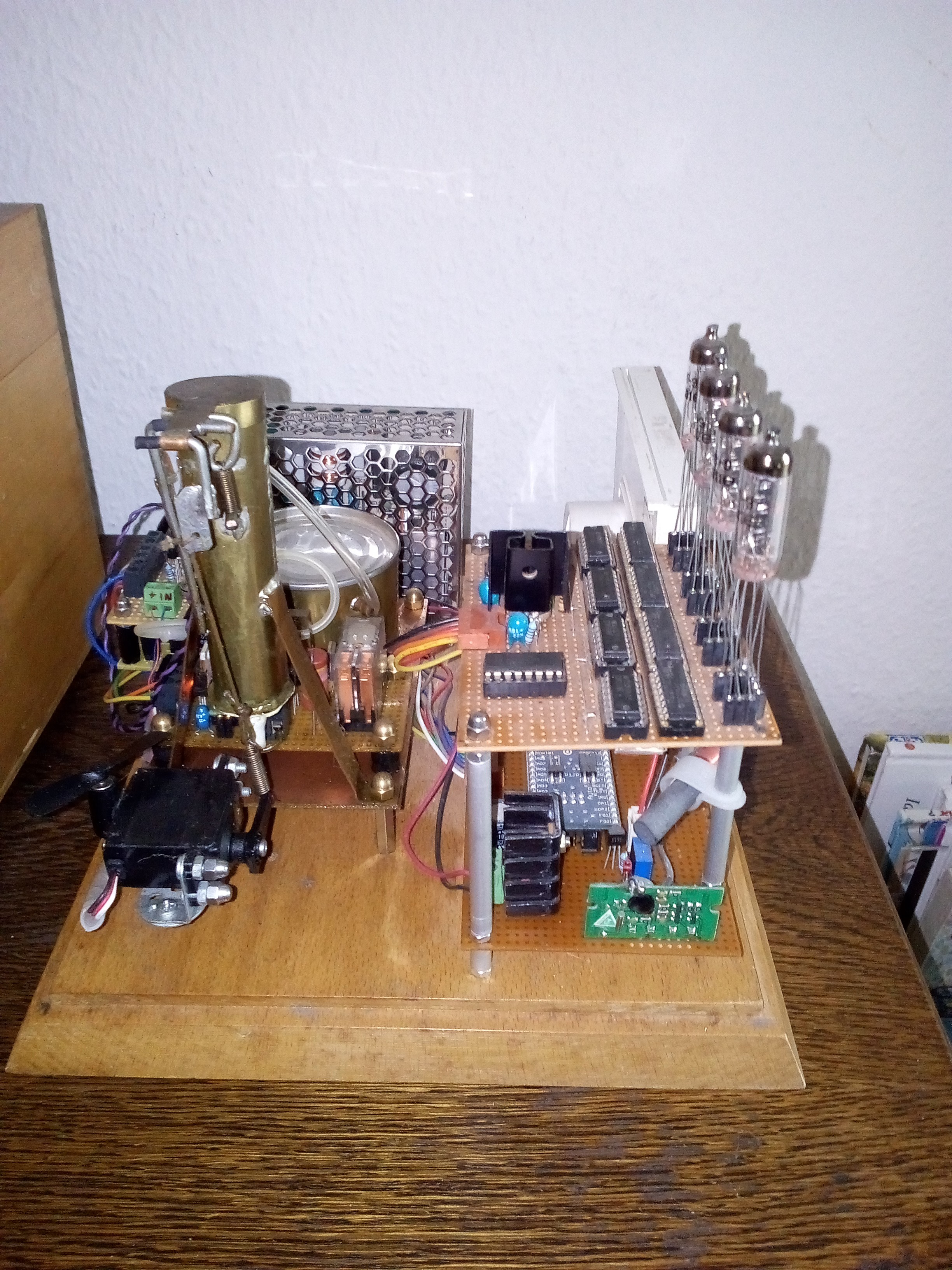
The Steam Clock consists out of 4 subsystems:
- Power supply from 230 V to 12 V with 3 amps.
- Steam generator with steam oil tank, small controllers for motors, servo etc., pump and mechanics.
- Microcontroller board C-Control Unit 2.0 with Numitron display for hours and minutes, DCF 77 receiver, port expander and BCD controllers with drivers for generating the numbers.
- Coil indicating instrument for the seconds.
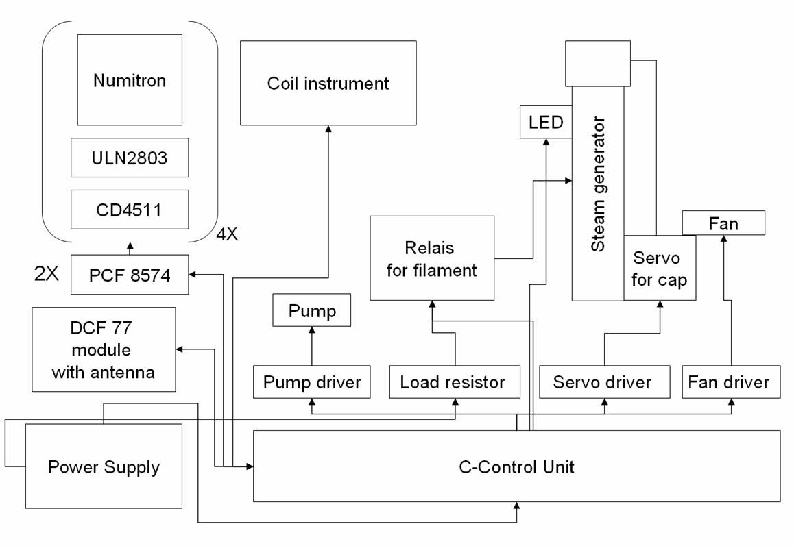
Simple overview about the Steam Clock
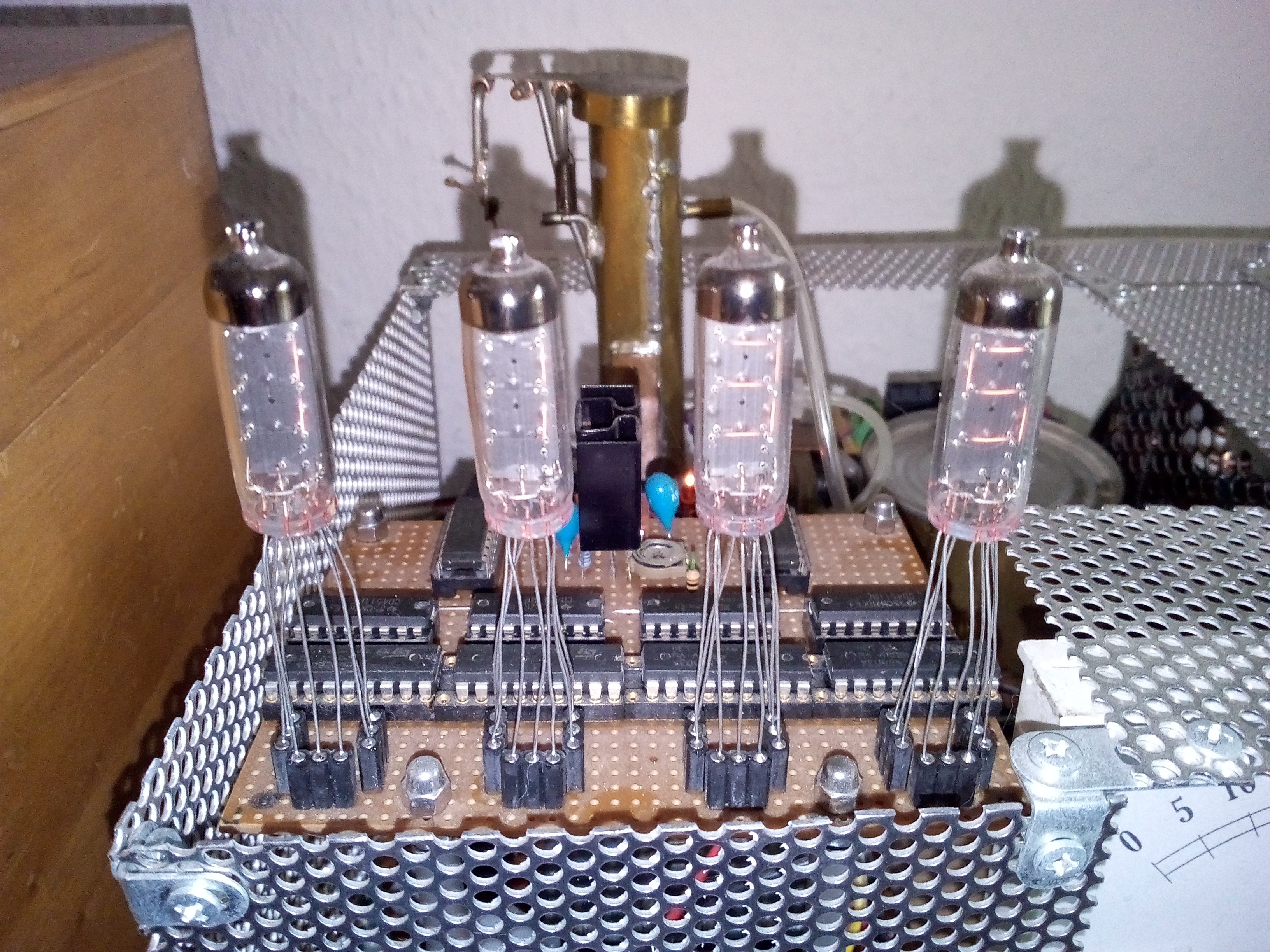
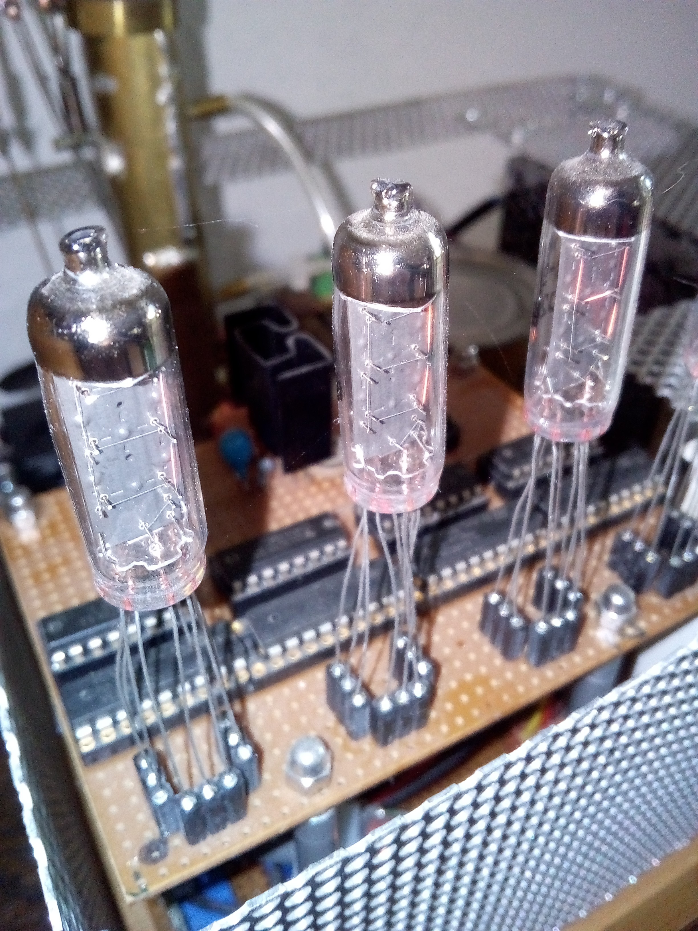
Numitron Display
To visualize the hour and the minute four Russian Numitron IV-9 tubes were used. Datasheet: http://www.tube-tester.com/sites/nixie/data/IV-9/iv-9.htm
Two PCF 8574 receiving data over I2C bus from the C-Control 2.0 Unit and split the most and least significant four bits for the most and least significant digit in the hour and minute part of the display. Datasheet: http://www.ti.com/lit/ds/symlink/pcf8574.pdf
After the two port expander each Numitron tube gets a BCD to seven segment controller like the CD 4511. Datasheet: http://www.ti.com/lit/ds/symlink/cd4511b.pdf
To drive the Numitron tubes I choosed the ULN2803. Datasheet: http://www.alldatasheet.com/datasheet-pdf/pdf/12687/ONSEMI/ULN2803.html
With this chip I was able to control the brightness of the tubes with a LM317 as voltage regulator. Datasheet: http://www.ti.com/lit/ds/symlink/lm317.pdf
To adjust the voltage a simple PCB mount potentiometer was used.
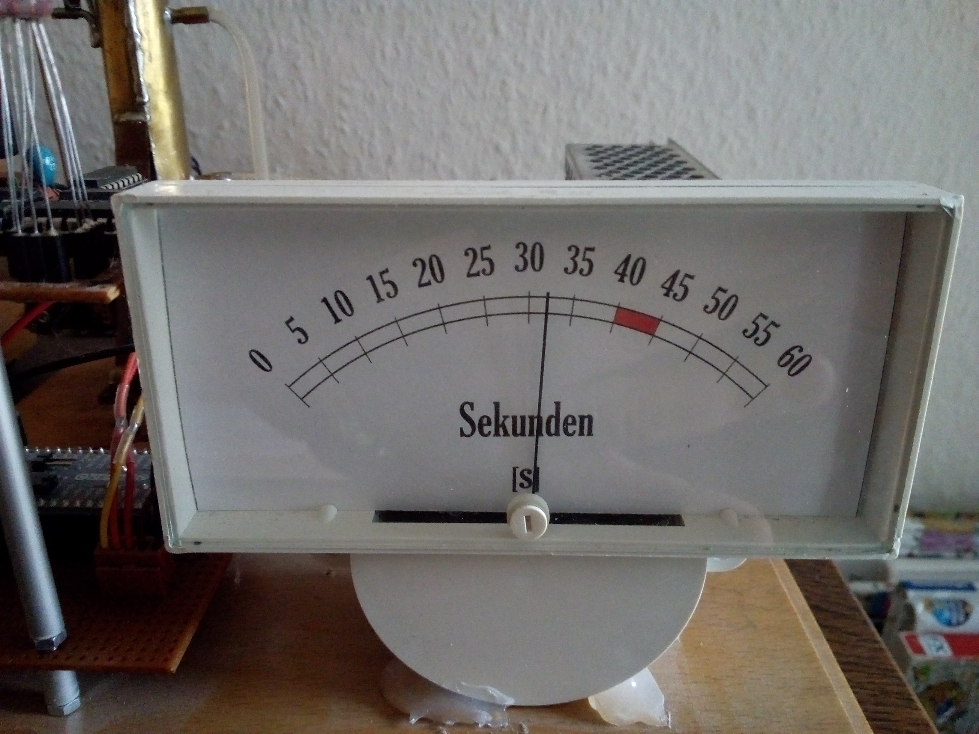
Coil indicating instrument
I love this old method to visualize currents, volts and other values. So I thought that it will be a good idea to use such a display for the seconds in a retrograde way. (A short time I was owner of a Wostok watch with a retrograde second hand but the caliber was crap so I gave it back.) A small potentiometer behind the coil instrument is used for the calibration of the action radius of the second hand. The voltage for the second hand was provided by the PWM of the C-Control Unit. For smoothen the movement of the second hand a 10 µF capacitor was installed in parallel to the coil of the instrument. The unit sheet inside the coil instrument was designed with Powerpoint and printed with a standard laser printer. The section between second 40 and 45 was coloured with a red marker pen. This section indicates the display of the date with day and month on the Numitron tubes.
 alcor6502
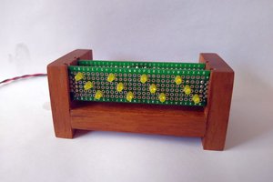
 danjovic
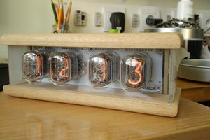
 Andy
Andy
Super nice design! Don't know if this video is applicable. If not it is interesting anyway.
https://www.youtube.com/watch?v=tiLzI7hm8M0